VSP-P1 User Manual
General
This user manual provides instructions for the set-up, installation, operation, and maintenance of the VSP-P1. The instructions are designed to ensure productive use of the equipment and to ensure the safety of personnel and equipment. Even though care has been taken in the preparation and publication of the contents of this manual, we do not assume legal or other liability for any inaccuracy, mistake, misstatement or any other error of whatsoever nature contained herein. The material in this manual is for information purposes only and is subject to change without notice. The manual will be updated to be in accordance with new releases on supported software or hardware. These new versions are available at docs.vsparticle.com . Please send suggestions, comments, and complaints regarding this user manual to support@VSPARTICLE.com with the subject line: “User manual VSP-P1”.
| Company | VSParticle B.V. |  |
|---|---|---|
| Address | Oostsingel 209 2612 HL Delft The Netherlands | |
| Website | vsparticle.com | |
| Support e-mail | support@vsparticle.com |
Symbols used
The following notifications are used in this document:
Notification: Blue notification blocks in the text highlight points of attention regarding the documentation.
| Warning: Yellow warning blocks with the caution symbol are used to highlight specific risks that require operator attention. |
| Caution: Red bounded blocks with the caution symbol indicate a dangerous situation with immediate impact. |
Important safety information located within the manual is labelled with the caution symbol. Wherever a caution symbol is affixed to the machinery, there are explanatory texts located within the manual.
Intended Purpose
The VSP-P1 is designed for day-to-day operation in an industrial (lab) environment. It is used for the production of patterned nanostructured material on substrates. This device is intended for professional use.
System and operator safety
The risks associated with aerosol-based nanotechnology can be divided into two categories: those associated with the machinery itself, and those associated with nanoparticles. Machine-related risks are widely regulated by international norms, such as the European conformity system required for marking certain products with the CE symbol. However, synthesized nanomaterials are relatively new and their quantum effects are still being studied, thus there are fewer standardized measures in place. Until more is known about nanoparticles, we apply the Precautionary Principle, treating them as potentially highly toxic materials. The safety measures we employ for working with, storing and transporting nanoparticles have been drawn primarily from those designed for fine and ultrafine particles.
Safety of machinery
The VSP-P1 Nanomaterial printer comprises general electronics (<50 V), a mains guide (<250 V), gas connections and moving parts. Several safety mechanisms mitigate the risk of damages and incidents related to potential equipment failure, but the primary responsibility for correct and safe operation lies with the operator of the system. The VSP-P1 is intended for use by qualified personnel, which means people who received training from either VSPARTICLE or from someone trained by VSPARTICLE.
Operator safety actions
Operators are required to ensure that:
- The printer is correctly set up (see chapter 4 Installation).
- Use of the VSP-P1 is in accordance with the protocols set up in Chapter 6 Operating procedure.
- The pressure in the system is limited to 1.2 bar max. Operators should not override the automatic safety features designed to keep the system from reaching above 1.2 bar.
- All, if any, external safety systems are functional (where applicable).
- Personal protective equipment is being used correctly (gloves, glasses, and FFP3/P3 certified filter mask).
- Surfaces exposed to nanoparticles are not touched without proper safety precautions.
- The operator is trained to operate the VSP-P1 & VSP-G1 devices (further details on operating the VSP-G1 are located in the VSP-G1 Manual).
- The VSP-P1 is solely used for its intended purpose.
- The electronic cabinet of the VSP-P1 is properly closed (using the hex bolts provided) to prevent exposure to electrical equipment.
- The side and back panels of the VSP-P1 are not removed during operation.
- A leak test (see Chapter 6.5 Leak test) is always performed before starting the spark.
- The print chamber is always flushed before opening the chamber.
- The VSP-P1 is not disconnected from any of the gas in or outlets during a print procedure.
Stop button
A black latching switch pauses the XYZ stage and closes the print valve so an operator can timely pause a deposition process to avoid material damage. This button is not an emergency stop, does not cut power to the VSP-P1 or VSP-G1 and does not protect against exposure hazards.

Existing protective features
| Warning: Intentional misuse of the VSP-P1 in a manner not specified by VSPARTICLE may impair the existing protective features. |
The VSP-P1 has several protective systems in order to automatically mitigate operating risks. These measures do not relieve the operator from their responsibility to monitor the device but act as an additional layer of defense against hazards.
The VSP-P1 is equipped with an interlock system that, when the print chamber door is open, cuts power to the print stage and to the flow controllers, halting mechanical movement in the print chamber and cutting off nanoparticle transportation.
The VSP-G1 is also equipped with an interlock system. When a failure is detected, the interlock system cuts power to the high-voltage supply and the motor, shutting down particle production. There are two types of interlock in the VSP-G1.
1. VSP-G1 internal Interlock
During start-up and while running, the VSP-G1 the control system checks if internal systems are working properly. If any check fails an internal interlock is triggered. When the interlock cuts power, you must first fix the conditions that caused the interlock to activate before clearing the interlock state. Press and depress both dials simultaneously to clear the interlock.
2. VSP-G1 reactor interlock The VSP-G1 detects whether the reactor endcaps are properly mounted, using two mounting pins (see image). You must ensure that the reactor itself is correctly assembled. In short, this means that the reactor is leak-tight (see the G1 operating and maintenance guide) and that the gas inlet valve and electrode tips are free to move with a minimum clearance of 10 mm from any foreign objects (see the G1 section on process connections and the G1 section on flow configurations).
| Warning: Gas connections and other user-provided functions are not controlled by the interlock. |
Other residual risks
Operating sequence
| Warning: Custom operating sequences may result in damage to equipment and facilities or injury to personnel. |
In addition to automatic production sequences, the VSP-P1 system allows certain custom actions to be executed. While protections are in place to cover most known failure modes, it is impossible to cover all possible combinations of commands. The operator is responsible for evaluating the impact of custom commands on the safe operation of the device. The same applies to any user confirmation of manual actions (such as cleaning, opening doors, etc.), these should not be ‘clicked away’ out of routine.
Pressure
| Warning: Parts of the system may be at overpressure during or after use. Accidentally opening those parts can lead to direct exposure to (potentially) harmful process medium. |
Pressure within the closed system poses a serious risk when improperly handled. Increased pressure can be caused by an unintentional release of gas at high pressure, the closing of output valves while an input valve is open, clogged filters, spark obstruction, or a full deposition system. The system is protected against regular overpressure events, however, the operator must still be careful not to disconnect tubing while the system is at overpressure.
Pyrophoric materials
Metal nanoparticles can be extremely reactive, and can be pyrophoric (spontaneous ignition upon exposure to air). Controlled air-exposure is needed before opening the system in order to passivate any reactive materials. Check if such reactions are a potential hazard before starting your operating procedure.
Maintenance
| Warning: Performing custom maintenance of the VSP-P1 system can cause potentially harmful situations, and may result in damage to equipment and facility or injury to personnel. |
The VSP-P1 system should be regularly cleaned and maintained in order to preserve functionality and maintain consistency. Due to the different materials and material combinations that can be used in the spark generators, the cleaning procedures used might differ from regular cleaning standards. The operator is responsible for assessing the impact of custom maintenance on the safe operation of the device.
Nanoparticles will collect on the surfaces inside the VSP-G1 reactor, downstream piping and on all surfaces in the print chamber. Cleaning of these surfaces presents the largest exposure risk to operators unless they can be performed in a safe environment (e.g. a fume hood). Sealing used filters for disposal/recycling is largely dependent on the particular filtration system and local regulations.
Relocating the VSP-P1
Relocation of the VSP-P1 is possible using the provided castors on the device. If this is intended for short distances over flat ground, the following steps apply:
| 1. Shut down the printer using the software, then through the red main power switch on the right side at the back |  |
| 2. Unplug the power cable |  |
| 3. Close off the gas supply at the source/outlet and disconnect both gas inlets |  |
| 4. Disconnect both gas outlets, making sure to properly use PPE. |  |
| 5. Mount the closed end caps on all open gas connections (both on the bottom back and the top where the VSP-G1 is placed) to protect the system and prevent accidental nanoparticle exposure. | |
| 6. Ensure the print chamber door is properly closed. |  |
| 7. Open both side panels |  |
| 8. Use a hex key to open up the electronic cabinet |  |
| 9. Use a hex key to raise all 4 feet to a position where they will not bump into thresholds |  |
| 10. Remount the panels (electronic cabinet and side panels), ensure the grounding cables are remounted! |  |
| 11. Unlock the 4 castor wheels | |
| 12. Push or pull the system (preferably with 2 persons) to the destined location | |
| 13. Lock the 4 castor wheels. If you intend to use the VSP-P1, reinstall it by putting the feet back down, remounting the panels and reconnecting the ground, gas and power cables. If you intend to store the VSP-P1, mount closed end caps on all open gas connections to ensure dust does not accumulate in the system during storage. |  |
If the VSP-P1 has to be transported outside the building it is used in due to e.g. relocating a company or laboratory, the standard procedure is to clean the VSP-P1 properly before shipping, close off all gas connections as aforementioned, and then fasten the VSP-P1 onto a pallet for transportation. If such transportation would involve shipping by plane or ship, consult and apply the necessary procedures and regulations for unfixed heavy devices of up to 250 kg. The VSP-P1 contains no attachment points for fasteners, cables or other devices, and transportation considerations of the device should always account for it as unfixed. Lifting the VSP-P1 should not be done manually, and should follow the local workplace safety regulations regarding the lifting of unfixed devices of around 250 kg.
Repairing and troubleshooting
Repair and hardware troubleshooting procedures on the VSP-P1 should only be done by authorized personnel, such as the operator of the VSP-P1 or VSPARTICLE affiliated personnel. VSPARTICLE is not responsible for anomalous behavior due to third party modifications of the VSP-P1. In order to access key parts of the VSP-P1's internal infrastructure, several access panels are located on the sides of the device. Opening these access ports allows inspection of the gas infrastructure as well as the vacuum pump. On the lefthand side of the VSP-P1, a secondary tool-accessible port behind the regular panel allows access to a large part of the electrical infrastructure of the VSP-P1 (the aforementioned electronic cabinet). This port should not be accessed while the device is powered on. When experiencing problems, first consult the troubleshooting chapter 8 Troubleshooting.
Safety of nanoparticles and nanomaterials
Notification: The information provided in document is correct to the best of our knowledge, information and belief at the date of its publication. The information given is designed only as a guidance for safe handling, use, processing, storage, transportation, disposal and release and is not to be considered a warranty or quality specification. The information relates only to the particulate element of the materials in question and does not supersede or replace individual material safety procedures. The guidelines present in this document should always be applied on top of existing safety procedures for each individual material or component involved.
Nanoparticulate materials present additional safety challenges to the user/handler that should be considered on top of any existing safety requirements. Due to the substantiative difference between bulk material and nanomaterials, the health hazards posed can be different from the bulk form. This can require different test methods for hazard, exposure and risk assessment comparative to the bulk form. Each individual material or combination of materials can present new or poorly understood dangers to the user comparative to the bulk material. As such this document will not aim to assess any prevalent combination or specific substance, but will simply consider all nanomaterials as being nanotoxic. Nanotoxicity is considered as a (relatively) new category of toxicity, on top of conventional toxicity, which is determined by the effects of the particles on metabolism and the effect of their new properties. Nanotoxicity and regular toxicity can also co-exist under specific conditions. For any specific material intended for use, consult reliable sources for possible recent nanotoxicity data on your nanomaterial. If no sources can be found or provided, consider the material nanotoxic.
The main channels of exposure to nanoparticles are by
- Absorption through the skin,
- Ingestion, and/or
- Inhalation.
The primary measures taken to protect from hazards presented by nanoparticles therefore follow procedures regarding exposure based hazards with the following steps:
- Assess exposure to nanomaterials (based on e.g. the proposed OEL values by the WHO or the precautionary principle combined with the As Low As Reasonably Practicable (ALARP) principle)
- Control exposure to nanoparticles (e.g. by applying the Occupational Hygiene strategy to eliminate risks observed in step 1)
- Educate, train and involve people working with nanoparticles on the specific health and safety issues of these materials, and involve these people in all phases of risk assessment and control.
In order to provide effective control on nanomaterial dangers, adhering to the Occupational Hygiene strategy, the following steps are advised (cited from the TNW Nanosafety Guidelines ):
- Eliminate: do not work with nanomaterials.
- Substitute: replace the nanomaterial by another material.
- Isolate: immobilized in a matrix, on a substrate, contained in a closes system (reactor, glovebox)
- Ventilate: work in a fume hood or a ventilated cabinet/area
- Personal protective equipment: wear respiration protection and gloves.
Assuming the nanomaterials are an integral part of the process that cannot be eliminated or substituted, steps 3 to 5 apply. Note that the steps apply in hierarchy, Personal protective equipment (PPE) should only be considered as a last remedy, it is preferable that the exposure risk is minimized in earlier steps. Relying on PPE to fully protect oneself against exposure to nanomaterials is inherently dangerous due to the inherent ease with which nanomaterials penetrate most common PPE.
In order to ensure a minimum risk of exposure, filtering the exhaust gas of any reactor containing nanomaterials with HEPA filters. Ensure that the room that the reactor is contained in is on an isolated ventilation system equipped with filters that can handle nanomaterial. Ensure this system is checked and tested by measurement periodically or replaced regularly. A compromised filter can fill a room with finely dispersed nanomaterial instead of keeping people safe. Ensure the filters are mounted properly, are undamaged and cannot be bypassed.
Currently, there is no set guideline for nanomaterial transportation. Several nanomaterials guidelines from nanomaterial laboratories (TU Delft, MIT, Penn-EHRS, ISU, CHS) agree that nanomaterials can be transported like ordinary chemicals that present a hazard when exposed. Use closed, labelled, containers to avoid exposure during transport, and utilize the safety guidelines of the relevant material as well as the nanomaterial SDS if available. Check with the relevant transportation legislation if specific regulations apply to nanomaterials or have recently been developed. It is advised to keep up to date with potential regulation changes. Always consider the hierarchy of safety regulations, if a shipment would meet the safety criteria of a more stringent material (e.g. dangerous metals, solvents), those measures apply on top of the nanomaterial guidelines. It is advised to try and be up to date with changes within the international regulatory scope, such as new regulations on the subject by the International Civil Aviation Organization (ICAO), International Air Transport Association (IATA), International Maritime Organization (IMO), or organizations such as the ECHA, OECD, ISO, OSHA, EPA, and changes in laws or regulations such as the TSCA, REACH, CLP and other regulatory frameworks for dangerous materials. As of current, nanomaterials should be disposed of as chemical waste. Keep in mind the solubility of the material and act accordingly. If the nanomaterial is very soluble in water, adhere to the regulations regarding the disposal of the macroscopic material. In case of doubt, contact your local environmental agency for guidance.
Cleaning operations carry a high risk of exposure, maintain vigilance and adhere to strict protocols. Use PPE and work in a fume hood if the equipment allows this. Ensure the fumehood is also cleaned afterwards. Dispose of any contaminated material as chemical waste. If a fume hood cannot be used or has to be open to fit contaminated equipment, wear respiration protection and consider overall protection. Solid surfaces can be cleaned using wet cloth, with the fluid medium dependent on the nanomaterial (water or solvent in general). Either dispose of the cloth entirely or rinse it properly, making sure that the runoff is treated as chemical waste.
In case of a spill, assess the size and hazard of the spill. Inhalation and dermal exposure are the greatest risks involved. If the spill is likely to have nanomaterial that might re-aerosolize, creating airborne particles the risk of exposure increases rapidly. A hierarchy exists here, with nanomaterial dusts and powders being more dangerous than liquids, and encapsulated or immobilized nanomaterials presenting the lowest risk of potential exposure. In general, the level of personal protection and cleaning methodology should closely resemble those used with asbestos. As such, establish a protocol with your safety department or Safety & health advisor on the proper way to report and handle spills.
In the event of exposure, or suspicion of exposure to nanomaterials, document the event and ensure this document is accessible to the person exposed and the party responsible for the conditions in which the exposure event happened. This document fulfils a purpose similar to the methodology around asbestos exposure events, as a reference in case of long term health effects. The following first aid recommendations are gathered from a specific guideline for laboratories: 1) If nanomaterials get into the eye, they shall be flushed and rinsed with plenty of water; 2) and 3) In case of inhalation or ingestion, they suggest gargling, washing and rinsing the mouth thoroughly, whereby for 2) inhalation, the movement to a clean air area and for 3) ingestion, spitting out is expedient; 4) If nanomaterials are adhered to the skin, they ought to be washed with soap or wiped off with cleansing cream (AIST & MHLW).
System description
General process description
The VSP-P1 is designed for the production of well-defined patterned nanomaterials, where particles suspended in a gas (aerosol) are transported from a particle source to a flat target substrate, and are deposited thereon. The VSP-P1 here is solely a deposition platform for the VSP-G1 nanoparticle source. In order to functionalize this, the device initializes a low vacuum in a controlled chamber. Typical conditions in the process are temperatures between 25 and 50 °C and low vacuum levels of 0.1~1 mbar.
As the VSP-G1 spark ablation reactor has independent documentation, this manual will refrain from repeating the material covered there.
From Particle material to Printed material:
Particle generation happens within the VSP-G1. Using the spark ablation method, nanoparticulate material is ablated from the electrodes and captured in a gas stream. This gas stream is then directed into the VSP-P1 NanoPrinter. In general, during a deposition process, it is advised to keep the VSP-G1 on during the entire process in order to stabilize the spark ablation process. In order to facilitate this, the VSP-P1 is outfitted with a way to control the deposition process without interrupting or affecting the spark ablation process. Normally, when ready to print, the VSP-G1 is constantly producing nanomaterial inside a gas stream while the print chamber of the VSP-P1 is in vacuum conditions. The aerosol flow from The VSP-G1 process is directed into the VSP-P1, where it is redirected towards the end filter and thus disposed of. This redirection is done using the ‘bypass gas’, a gas flow of the chosen carrier medium which blocks off the aerosol flow and exits the nozzle into the print chamber. When an operator directs the VSP-P1 to print nanomaterial, the aerosol is redirected towards the nozzle of the device. From the nozzle, the aerosol flow impacts upon a substrate inside the print chamber. Once an operator commands the VSP-P1 to stop printing, the bypass gas redirects the aerosol flow back into the end filter disposal. As this process involves gas flows, there is a delay involved between switching the printing mode and the physical system responding. This leads to several key points that are useful to recall as an operator:
- When engaged and ready for printing, there will always be a gas flow of the chosen carrier medium coming from the nozzle. This flow will only contain nanoparticles during printing.
- When switching the printing process on or off, the gasses will still have to travel through the system, inducing a short delay before the aerosol stream starts or ends. (usually within the order of milliseconds, depending on the chosen settings)
- After switching off printing, nanoparticulate material may not be fully eliminated from the gas stream, as some of the particles that have adhered to the insides of the tubes during the printing process can still escape into the gas stream.
- As long as the VSP-G1 is on and sparking and the VSP-P1 is ready to print, electrode material and carrier gas are being consumed. Whether the VSP-P1 is depositing the produced material does not affect this consumption.
System overview

The main components of the VSP-P1 are the print chamber with the print stage and printhead inside, the gas infrastructure and the control system. The VSP-G1 spark generator(s), that consist of a base unit and reactor chamber, is necessary to run the printer and will be treated like a subcomponent within this manual.
Main components
The VSP-P1 contains several key components which an operator should familiarize themselves with:
VSP-G1 nanoparticle generator
| Warning: Caution – Independent risks: Consult the VSP-G1 user manual for the associated risks and procedures needed to operate a VSP-G1 before operating the VSP-G1 on a VSP-P1. |
The VSP-G1 creates the nanoparticle aerosol by repetitively evaporating a small amount of electrode material with electric discharges (sparks).
The user manual of the VSP-G1 can be found here: VSP-G1_User_Manual
While mounted on a VSP-P1 nanomaterial printer, the VSP-G1 can be controlled completely by the VSP-P1. While connected to a VSP-P1, the independent VSP-G1 controls will be locked in favor of the VSP-P1 controls in order to prevent potential accidents. While operated, the reactor is mounted on top of the VSP-P1, connected to the gas infrastructure and print chamber of the VSP-P1.
Print chamber
| Warning: Caution – Nanoparticle exposure: Do not open the print chamber if the flush procedure is not completed |
The print chamber is a vacuum chamber that is connected to a vacuum pump. Periodically, the filters between the print chamber and this pump should be replaced. When switching between materials to deposit, it is advised to clean the print chamber thoroughly to avoid cross-contamination. The print chamber contains a vacuum feedthrough that powers and communicates with the devices within the chamber. Operators aiming to utilize custom equipment inside the chamber using this feedthrough should contact VSPARTICLE to explore the possibilities.
Print chamber door
The door of the print chamber is locked using three rotatable clamps. The clamps operate using a push & twist mechanism. After positioning them correctly, a user will have to push them and then rotate the handle to lock the door. All three handles need to be properly closed before the door will seal properly. If the print chamber does not appear to be leak tight, check if the door is level to the sealing surface and closed properly. The door interlock sensor is located opposite of the door hinge, and should not be obstructed.
 |
 |
Print head
The print head is the deposition side of the gas infrastructure. It consists of a flange mounted assembly that ends in a print nozzle, mounted on a bracket. This bracket provides support and centers to the nozzle.
In order to switch from depositing one material to some other material, a general cleaning process is advised on the entire printhead assembly, both the bracket and mounted parts as well as the nozzle and the entire flange based gas infrastructure. The easiest way to clean the printhead is by performing a gas cleaning procedure. If this is not sufficient, the gas infrastructure assembly inside the print chamber can be removed using the flange. Detailed instructions are available in the manual chapter 7 System care and maintenance.
LED array
The print chamber contains an array of LED lighting, illumination the inside of the chamber. This chamber lighting can be turned off in the user interface if needed.
Nozzle
The nozzle is removable without having to take out the entire print head, allowing operators to switch nozzle types.
 |
 |
The nozzle contains three parts, an O ring, a nozzle holder and a nozzle insert. Henceforth the term “nozzle” is used mostly to indicate the nozzle insert, which is the part that dictates the deposition orifice used, and as such the flow rate. The nozzle holder and O ring can be used in combination with any of the nozzle inserts delivered with the P1. The VSP-P1 is delivered with three nozzle sizes, listed in the table below. Smaller nozzles allow printing with a smaller spotsize, but support a lower flow rate, generally resulting in less material output. Because of the different flow rate, the chamber pressure also depends on the nozzle.
| Nozzle type | Bore size | Flow rate (Ar) | Chamber pressure (Ar) |
|---|---|---|---|
| 004 | 0.1 mm | < 0.08 slpm | 0.1 - 0.2 mbar |
| 054 | 0.2 mm | 0.2 – 0.3 slpm | 0.3 - 0.4 mbar |
| 125 | 0.35 mm | 0.8 – 0.9 slpm | 0.7 – 0.8 mbar |
When the deposition pressure is not inside the listed range, please refer to the troubleshooting section. A lower deposition pressure might for example be caused by a clogging nozzle. By cleaning the nozzle regularly, this can be prevented. The nozzle type number is visible on the nozzle.

Camera
The VSP-P1 is equipped with 2 camera’s. One overview camera for quality control of the printed substrates (optical zoom 2x) and one precision camera for alignment of the substrate and print pattern (optical zoom 10x). These cameras are mounted on the same bracket as the print nozzle. They are, however, not in line with the print nozzle. In order to move from the camera spot to the actual print spot, the operator would need to command the stage to travel there. For the exact translation between camera and nozzle, see the chapter alingment of the nozzle.
The reach of the cameras cannot cover the entirety of a mounted substrate holder, it is therefore advised to prioritize placing substrates near the middle or the top of the substrate holder.

Substrate holder
| Warning: Substrate holders are precision devices. Handle with care and do not drop, bend, adjust or damage in any way to ensure consistent production. |
Substrates can be mounted outside of the VSP-P1 (in a fume hood) onto the substrate holder. Substrate holders are placed on the substrate holder baseplate. Substrate holders can be adapted for specific products, and are individually calibrated. Do not adjust calibration screws and or settings.
Substrates can be fixated on the substrate holder using the clamps or, when the clamps are not suitable, a suitable adhesive can be used. The substates should be properly fixated on the holder, since the strong aerosol jet from the nozzle might otherwise blow them away. Also it is advised to make sure they are flat, to maintain a constant print height over the substrate.
Print stage
| Warning: Mishandling the substrate stage can cause misalignment or damage, resulting in rejected product. |
The print stage consists of an XYZ stage mounted in the print chamber. This stage accounts for all the movement made during deposition, as the nozzle is fixed and does not move. The stage operates using a threaded system intermeshing stepper motors with axes. The stage can move in three dimensions and allows coordinated motion. When the stage encounters an obstruction, it will stop after reaching a certain torque limit. In order to make moving towards the nozzle easier, a stepper function that operates at lower torque limits is used in the GUI. This means that an operator should always take care when moving the stage upwards toward the print nozzle (such as by using the provided Z step function). While the stage does include a torque limitation feature, it is advised to never obstruct the stage's movement as the motors may still damage the obstruction. The stage does not operate when the print chamber door is opened, allowing users access to the stage safely. This does mean that an operator will be unable to adjust the position of his substrate using the stage as long as the door is opened. The stage will report the temperature, speed and status for each motor in the GUI of the VSP-P1. The status is reported by each individual motor, several instances might require action from the operator:
| Motor status | Function | Possible required actions |
|---|---|---|
| Active, in position | Indicates the motor is active and enforcing its current position. The motor will resist attempts to move it. | No action required |
| Motor Free | Indicates the motor is inactive. | If unintended, the motor might be turned off in the GUI. |
| Active, running | Indicates the motor is actively following commands to move. | No action required |
| Overload | Indicates the motor has started to draw excessive current and shut down as a safety precaution. This can happen when the motor runs into a physical obstruction or breaks down. | When encountering an overload, turn the motor on and off, then check if the stage has encountered a physical constraint such as the ends or bottom of the stage or an unexpected obstruction (e.g. custom devices, cables, etc). If such, move it away from the obstruction or limit. If the motor hasn't encountered an obstruction and stops physically moving after resetting (even if it reports that it is "running"), contact VSPARTICLE for troubleshooting. |
| Temperature Alarm | Indicates the motor has become too hot. The motor automatically enters this state if the motor temperature exceeds its set limit. This will disable the motor until the motor cools down to 10°C below its limit. | The VSP-P1 will perform emergency actions before a temperature alarm is reached. If you see the temperature alarm message on the motor status UI, contact VSPARTICLE. |
Note that during the deposition process, the stage heats up due to the vacuum. The substrate holder is roughly 45-50 °C when the motors reach a steady state at around 80 °C after 8/9 hours of running. It is advised that operators use a test run of a specific script before actual deposition in order to better understand the movements the stage makes and potential obstructions. If it appears like the stage will run into an obstruction, use the stop button on the front of the printer to stop the stage. This will pause all movements of the stage and close the print valve.
 |
 |
Vacuum pump
The VSP-P1 uses a Leybold Ecodry 65 oil free vacuum pump to create the necessary low vacuum for deposition. In order to ensure the vacuum pump remains operational, adhere to the maintenance schedule in 7.2 Maintenance schedule and check if the HEPA filter keeping particles from entering the pump is close to clogging, and if so, replace it. Furthermore, ensure the print chamber does not get contaminated with fluids that could get sucked into the pump, as this is a dry pump. The pump is controlled through the GUI of the VSP-P1, where it is turned on when going into the ‘printing’ state. The vacuum pump will need about 3 minutes to generate the low vacuum conditions suitable for deposition. This will be regulated automatically. The pump needs to remain on during deposition, but if an operator is planning to initiate procedures in which the deposition process finishes well before the operator can remove the samples from the VSP-P1, it is advised to turn the pump off once the deposition process finishes.

Below is an excerpt from the Leybold manual in regards to hazards that should be avoided:
Non-conforming Use
 The ECODRY plus is not suited for pumping of:
■ Radioactive substances
■ Explosive substances
■ Ignitable gas mixtures
■ Pyrophorous gases
■ Liquids
■ Media condensing in the pump
■ Solids/dusts
■ Oxidative substances with the exception of ≤ 21% oxygen in the air
■ Toxic gases belonging to GHS category I and II
 Pumping of the following gases is only permissible after having consulted
 Leybold first:
■ corrosive gases
■ toxic gases belonging to GHS category II and IV
 When pumping toxic gases replace the gas ballast switch with a plug screw or connect a gas supply to the gas ballast
Control panel
The complete system is controlled via the control panel on the VSP-P1 or remotely via a web interface. See Graphical User Interface for the details.

Gas infrastructure
Mass flow controllers
The VSP-P1 gas infrastructure uses a couple of mass flow controllers (MFC's) to regulate the deposition process. These flow controllers include a pressure sensor as a monitoring feature. When the pressure sensors detect a pressure above the pressure limit, the MFC's will be stopped to prevent the system from developing overpressure. The MFC's are located on the side of the VSP-P1 near the electronics cabinet and can easily be accessed for maintenance or safety checks.
 |
 |
End filter valve
The end filter valve is used to pressurize the system when performing a leak tests and to prevent backflows into the device during the flush procedure and when vacuum is preserved without flow. The End filter valve is controlled by the VSP-P1 control system, and operators will not need to use it independently.
Vent valve
The vent valve is used to vent the print chamber or contain its vacuum and is controlled by the VSP-P1 control system. By opening the vent valve the chamber is repressurized, allowing a free flow from any medium through the Air/flush inlet via an HEPA filter into the print chamber.
Gas inlet valve
The Gas inlet valve is used to block the gas supply connected to the VP-P1 for maintenance or in case of emergencies. During ordinary operation the gas inlet valve is open and allowing flow at all process steps, as the MFC's already block any unwanted flows from entering the print chamber. Only in the event that the VSP-P1 control system detects an emergency, will the gas inlet valve be closed.
Print valve
The print valve controls the ‘bypass gas’ that, as described in more detail in General process description, is used to redirect the nano aerosol into the end filter disposal. This allows to toggle printing and ‘not printing’ while maintaining a constant flow through the nozzle. The print valve is labeled as ‘open’ when it directs the clean bypass gas into the end filter, allowing for the nano aerosol to enter through the nozzle and deposit on the substrate. It is labeled as ‘closed’ when it directs the clean bypass gas into the nozzle, redirecting the nano aerosol to the end filter and thus stopping the particles from being deposited. The print valve can be opened and closed by respectively entering v.open or v.close in the GUI command window, as this functionality is mainly used within automated print scripts.
Top light
On the top of the VSP-P1, around the flange on top of the vacuum chamber, is a circular light that indicates if the VSP-P1 is on.
Installation
Enviromental requirements
| Caution: Caution: In case of exposure to electricity using the VSP-P1, turn off the power using the (red) power button on the back before touching the affected person. |
The VSP-P1 may only be installed by qualified personnel in a well-ventilated environment. Proper precautions need to be in place to ensure operators are informed if ventilation fails during installation or use of the VSP-P1. An even and solid surface is required to station the VSP-P1 on. Ideally this floor is easy to clean and does not react with chemicals or cleaning agents that might be used by the client during operation of the device. Ambiently, the VSP-P1 should be stationed in a controlled indoors environment of room conditions (this excludes cabinets or other confined spaces). To ensure there is no risk of suffocation or nanoparticle exposure, the room the VSP-P1 is stationed in must be sufficiently ventilated. The end user is responsible for determining what constitutes 'sufficiently ventilated', taking into account their specific situation, and any local laws and/or regulations. The VSP-P1 is equipped with HEPA filters to filter hazards from the output of the system. Nonetheless, it is recommended to connect the outputs of the VSP-P1 directly to the ventilation system (with adequate filtration) in order to minimize any potential chance at exposure. During installation, ensure that the VSP-P1 and the cabling connected to the device are free from obstructions and are not constrained in such a manner as would impede the in or outflow of gases or the ability of operators or maintenance personnel to access the device. When stationary, VSP-P1 should be mounted on both the support feet and the wheels mounted on the bottom of the device.
In order for the VSP-P1 to function properly, the following will need to be connected:
- Gas inlets
- Gas outlets
- Power cable
- Ethernet cable
Gas connections
The VSP-P1 nanoparticle printer is equipped with several gas throughputs required to operate the internal gas infrastructure. The deposition process used in the VSP-P1 requires a flow of carrier gas to operate and a flow of flush gas in order to repressurize the print chamber. As waste products, a flow of carrier gas filtrated through a HEPA filter is expelled from the VSP-P1's exhaust, as well as a flow of waste gas from the vacuum pump (similarly filtered). Although the HEPA filters mounted in the VSP-P1 are generally efficient at removing nanoparticles, the nature of the material requires the operator to have a failsafe.
| Warning: Caution – Exhausts:No VSP-P1 exhaust should be left open to a room, all exhausts on the VSP-P1 should be connected directly to a ventilation system that provides sufficient filtration to remove nanoparticles. |
Unrated Gas safety rules
The VSP-P1 is rated for the following gas mediums at room temperature*:
- Ambient indoor air
- Nitrogen
- Argon.
When using other gasses in the VSP-P1, several safety measures apply:
- the Four eyes principle** must take place (e.g. for reactive gases like H2/O2/CH4)
- Operators should be familiar with the gas supply of the facility, in particular operators must be able to check sufficient gas is in supply.
- Consult the Manual of the Leybold Ecodry pump. If the new gas does not conform to the intended use of the Leybold pump (Leybold manual section 3.2.1. Non-conforming Use, also copied in this manual section Vacuum pump), consult VSPARTICLE for advice.
Do not hesitate to contact VSPARTICLE for advice or support in safety decisions regarding the VSP-P1.
- (Contact VSPARTICLE for advice on the usage of specific gas medium temperatures)
- (The Four eyes principle is a requirement that two individuals approve some action before it can be taken.)

The VSP-P1 system has three gas input connections, each fitted with a 6mm G1/4 SERTO connection port. These are labeled as the gas inlet, the air/flush intake and the spare inlet.
Air/flush intake
The Air/flush intake is used to (re)fill the print chamber during flushing procedures or the final steps of production. Operators can use this inlet to pressurize the print chamber after production. The connection from this intake to the vacuum chamber contains a HEPA filter and a valve. If used normally, the intake should be unobstructed and allowed access to clean air. If the end user desires a different pressurization medium, the SERTO connection on the intake will allow the operator to connect a different gas source using a ø6 mm ED hose with a SO 50021-6 SERTO nut connection coupling (use appropriate stiffeners in case of flexible tubing). The end user is responsible for determining safe pressurization mediums.
The male SERTO inlet connector on the VSP-P1 can be used to connect to ambient air or to a controlled gas source. For ambient air, use an open SERTO female connector piece. When using unrated gas mediums for this inlet, adhere to the previously mentioned unrated gas safety rules.
Gas inlet
The gas inlet is used to supply the VSP-G1 systems with a carrier gas for the generated nanoparticles. The VSP-P1 has space for two VSP-G1 systems. This inlet leads to the mass flow controllers within the VSP-P1, which subsequently connect to both the VSP-G1's and the printing system. These systems require the source connected to the inlet to be pressurized at 1.5 bar. The connection towards the VSP-P1 is identical to that of the air/flush intake, and so similar measures can be used to connect the gas source, the 6 mm external diameter tubing with SERTO connections.
| Warning: Enabling or attempting to control gas flows without a VSP-G1 connected to the VSP-P1 system can result in leaks. Ensure that all unused connections are closed off properly! |
For installation purposes, ensure the pressurized gas source is closed off during installation. Use the provided SERTO connections to establish a connection between your source and the VSP-P1. Ensure the connection is tight by utilizing spanners on the provided surfaces. Always ensure one spanner is blocking the inlet from rotating while you tighten the connection. After connecting the gas source, the valves in the VSP-P1 will block the flow, allowing you to keep the gas source open while the system is inoperative. Due to the overpressure present in this connection, leak spray can be used to perform a preliminary check on the connection.
After the VSP-P1 has been installed, initiate a system leak test to check for leaks within the connections. This procedure should be repeated any time an operator changes the connections in order to ensure safety and production consistency. The leak-test procedure is described in Leak test.
Spare inlet
This inlet does not connect with anything within the regular VSP-P1 model, and is included solely to provide a platform for further customization within the VSP-P1. Consult VSPARTICLE for options regarding the usage of custom setups.
Outlet Pump
The pump outlet connection is used as an exhaust by the vacuum pump. Air pumped out of the print chamber will come out of this outlet after having been filtered by a HEPA filter
This air should still be considered as potentially dangerous. The provided KF flange allows the operator to connect several different forms of tubing to this outlet (with the same cross sectional area). These tubes should lead to a general ventilation assembly that can further filter the air.
Below an excerpt from the Leybold pump manual:
The cross-section of the exhaust line must at least match the inside diameter of the connections. Smaller cross
sections may cause an undesirable overpressure within the system. Do not start up the pump with a constricted or
blocked exhaust. Ensure that any valves or blocking devices in the exhaust line are open.
Clogged exhaust lines will reduce the available pumping speed, increase
temperature and cause overloading of the pump motor or a dangerous
overpressure within the system. There is the risk of bursting. The pump
can generate pressures up to 5 bar (abs.) at the exhaust, when the discharge line is shut.
Outlet end filter
| Caution: Caution – Nanoparticle exposure: Do not use the VSP-P1 while the outlet end filter or pump outlet is open to the environment. |
The end filter outlet is used as a general exhaust of the VSP-P1 system, all the unutilized particles as well as bypass and choked carrier gas flows will eventually end up at this outlet. While an HEPA filter is installed on this outlet, the outlet should never be open to the ambient environment while the VSP-P1 is in use. The KF 16 flange on the outlet allows the operator to connect the outlet directly to the ventilation system used to remove nanoparticles from the environment. Always ensure that the different compounds that might enter the ventilation system are known, as to ensure that the particles or gas coming from the end filter outlet of the VSP-P1 do not combine in a dangerous manner with other contaminants in the ventilation system.
Electrical connections
A mains cable rated 220V / 16A provides power to the system. The main power inlet is located at the back bottom of the printer. Next to the power inlet the ethernet connection inlet is placed. Instructions on how to connect the VSP-P1 to a network through ethernet connection can be found in chapter 4.5. Above the ethernet connection and the power inlets the user can find the main power switch.
 |
 |
The VSP-P1 can be powered using AC 200-240V ±10%, 50-60Hz and its power consumption reaches maximum 1.6kVA.
To connect the printer to power grid of 110-120V a proper converter is needed:
- Input voltage = 110V
- Output voltage = 200-240V (50-60 Hz)
- Power = 1.6kVA
On the top part of the printer, two G1s can be placed. For the G1.1 to be powered through the printer, the cable labelled M-80000946 coming from the printer needs to be connected to the power inlet of the G1.1. The communications cable M-80000947 also needs to be connected to the G1.1. The respective cables for the second G1 (G1.2) are M-80000948 (power) and M-80000949 (comms).
VSP-G1
The base unit with reactor installed has a combined weight of 22kg. For general handling, e.g. when assembling a setup, due to ergonomic reasons, the reactor should be transported separately from the base unit. A mounting plate / transport tool is provided for this purpose. See unmounting the reactor assembly of the operating and maintenance guide. The base unit can be placed on the working surface of the VSP-P1. Place the base unit with the controls facing outwards, away from the center of the VSP-P1 and slide its feet into the slotted holders on top of the working surface. Once the base unit is installed, the VSP-G1 reactor can be mounted onto the baseplate using the appropriate measures as directed in the manual of the VSP-G1. To connect the VSP-G1 to the VSP-P1 after placing it, the base unit needs to be connected to the proper electrical connections, and the reactor has to be connected to the gas infrastructure of the P1. Two blue gas tubes extend from the back of the worksurface of the VSP-P1, extending to both sides. These supply the VSP-G1 with carrier gas. One of these should be connected to the front of the reactor, upstream of the sparking process for each G1 that is being used respectively. Similar feedthroughs extend from a t-split piece on the flange that connects to the print chamber. Again, for each respective VSP-G1 connected to the system, one of these connections should be utilized. If one uses only one VSP-G1, the remaining connections should be closed off using SERTO end connectors. The electrical connections that power and control the VSP-G1 also extend from the back of the worksurface. There are two connections respectively, a C13 power connector and a RS 232 cable pin communication cable. Both of these need to be plugged into the base unit of the VSP-G1. The VSP-G1 has an insulation rating of class I and is compatible with the VSP-P1 out of the box without any adjustments.

The Gas connections leading to the G1 are labelled corresponding to their GUI variants. Operators should block unused G1 feed gas cables and Print chamber inlets so that they cannot leak accidentally.
Connecting the VSP-P1 to a network
The VSP-P1 offers two methods to connect the system to a network: an existing network, or a hotspot. It is generally recommended that the VSP-P1 is connected to an existing network. This offers the easiest method to connect from e.g. the user’s work computer. The hotspot is primarily used for the initial configuration or when no existing network is available. The connection to an existing network can be set up while connected to the hotspot. Out of these options, VSPARTICLE recommends connecting to an existing network using an ethernet cable for stable GUI & update functionality.
Connecting to the VSP-P1 Hotspot
The VSP-P1 sends out its own WiFi network. It is only possible to connect to this hotspot via WiFi. This is an easy method to connect to the VSP-P1, but since most work computers can only be connected to a single WiFi network at a time, not recommended for daily use. Using the hotspot generally prevents internet access on the work computer and involves extra steps to connect or disconnect. To connect your laptop to the VSP-P1 hotspot, on the VSP-P1 touchscreen, click on Settings and select Hotspot. On this page you can find the credentials to log in to the network that is sent out by the VSP-P1. An example screenshot is included. Note that sensitive information has been removed from the screenshot.

On a work computer, when specifying you want to connect to a new network, you should be able to see the WiFi network that is displayed on the VSP-P1 touchscreen. If not, make sure you are close enough to the VSP-P1 and try to connect again. The hotspot works best when within 10 meters of the printer and no physical obstructions block the signal. Connect to the network by providing the password shown on the touchscreen. All common operating systems provide out-of-the-box support and an easy method to connect to the hotspot provided the credentials above. Should specification of the type of WiFi connection be required, use WPA2-PSK (WPA2 pre-shared key).
When the connection is established, go to the IPv4 or IPv6 URL shown on the touchscreen using any internet browser. The IPv4 URL is shorter to type and works well on virtually all networks. The VSP-P1 user interface should show up.
Connecting to an existing network
The preferred method to make the VSP-P1 available on a work computer is by connecting the VSP-P1 to an existing network. There are two ways in which this can be done: via an ethernet cable (also known as UTP, LAN or RJ45 cable) or via WiFi. VSPARTICLE strongly recommends the use of ethernet as low latency and high throughput greatly improve the usability of the interface (e.g. camera views). Note that both methods might require the help of an IT person familiar with the network configuration of the lab in which the VSP-P1 is installed; many networks are secured to prevent unknown devices from connecting to them.
To connect the VSP-P1 to a network via an ethernet cable, insert the cable into the ethernet port on the back of the P1 (see 4.3). No further configuration is required.
Alternatively, to connect the VSP-P1 to a network via WiFi instead:
- Go to the Network Manager via Settings, then Network
- Click the name of the target network on the left-hand side of the touchscreen and click Next.
- Enter the required security information in the WiFi Setup page to connect to the network. The correct security information depends on the network supplied by the operator, and the specific connection requirements would follow the procedures used by IT personnel in the operator’s company to connect wifi devices. After putting in the required information, click Connect.
Be advised that when connecting to a new network, all old network configuration settings are discarded. The VSP-P1 will not remember networks it previously connected to after a new network has been configured.
To view the IP address assigned to the VSP-P1, use the touchscreen to go again to Settings and click Network. On the right-hand side of the screen, the table specifies which network interfaces are found and whether or not they are connected (eth corresponds to ethernet, wlan to WiFi). Take note of the IP address listed here.


To view the VSP-P1 user interface from a work computer, prepend http:// to the address and remove the /XX subnet suffix of the IPv4 addresses shown under network status. For example, if the assigned IPv4 address is 10.100.20.42/22, go to the address http://10.100.20.42. When using IPv6, no subnet is shown.
Graphical User Interface
GUI description
 The Graphical User Interface (GUI) is divided in several sections, containing a menu bar (1), controls (2), metric data (3) and event data (4). The metric and event sections are always available, the availability of the control sections depends on the current state of the print process. For more information on how to operate the printer, using these system states, refer to the chapter 6 Operating procedure.
Menu bar
The top of the GUI contains a black menu bar with the following features: Dashboard, Data, Settings, Power and CML patterning.
![]()
The Dashboard option will take you to the VSP-P1 interface. In 5.3 VSP-P1 controls, the five states will be described with the belonging features.
The Data option contains information about the diskspace, the opportunity to download the data and to clean up the disk.
To download the data from the P1 follow the following instructions:
To check available disk space, go to Disk space in Data menu bar. Here you can check what percentage is used and check how many megabytes are left on the disk space. It is possible that you are not able to download your data when disk space is extremely limited. The following steps allow you to delete data to free up disk space:
|

|
In Settings you can find the Time & Date, Network, Hotspot, and Licenses. In the Time & Date section the user can select the date and local time, and time zone. After setting the correct date, time, and time zone click on the save button. The device will take 30 seconds to fully reload the system to save the correct settings. In chapter 4.6 Connecting the VSP-P1 to a network you can find more information about how to connect to the Network, and Hotspot options. The licenses section will show a list of third-party libraries and packages the functionality of the system uses.
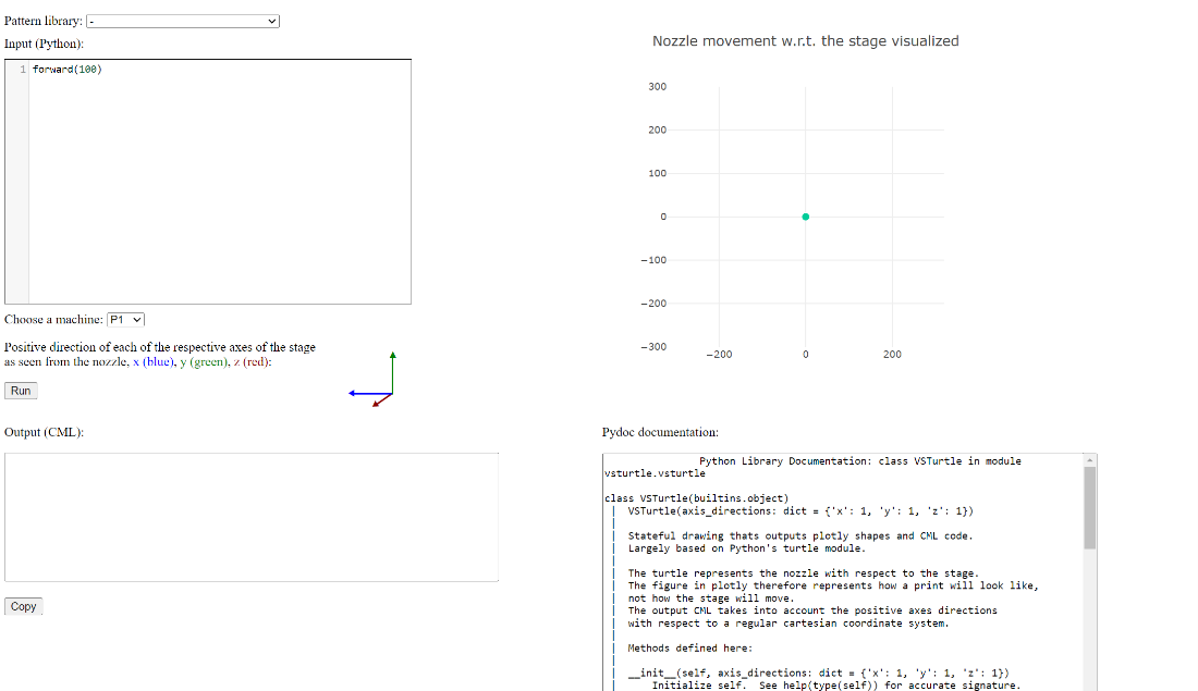
The CML patterning tool is a help tool to write patterning scripts. A python input (top left) is converted into CML code (bottom left) and visualized (top right). In the documentation (bottom right) can be found want syntax can be used for the python input.

The Power option can be used to turn off or restart the printer.
| Reload the system to restart only the control interface. This will not have any effect on running processes on the controller.
Reboot the system to restart the entire controller. This will stop all running processes (stop the pump, stage, flows and close valves). When it turns back on, a suitable system state will be determined according to available metric values. No processes will be resumed automatically. Press Shutdown to shut the controller down. Then switch the red power button to off, to power off the rest of the printer. |

|
Alerts are shown in the alerts dropdown on the right end of the menu bar.

VSP-P1 controls
The P1 control section is divided into several ‘system states’, shown in the progress bar in the top part of the section. The 4 main states are ‘Standby’, ‘System assembly’, ‘Prepare printing’, and ‘Printing’. Each state belongs to a different part of the print process, showing only the controls that are needed in the current state of the printer and blocking actions that are not safe. More information on how to control the printer, going through the different system states is described in chapter 6: Operating procedure.

Sending instructions to the printer
To send a command, fill in target values, or toggle the relevant function selector (see figure below). Check that the dropdown in ‘Apply’ is set to ‘now’, then press ‘Go’ to send the instruction. Sending delayed instructions is possible by changing ‘Apply now’ to ‘Apply in
 |
 |

|
XYZ print stage control
The print stage is used to align the nozzle and create patterns. Besides a general metric overview, three modes of operation are provided: Basic, Jogging and Script, as described in the following entries. To quickly stop the stage, when it is moving in an unwanted direction or is about to run into an obstruction, use the stop button on the front of the printer. This will pause all movements of the stage and closes the print valve. When the chamber door is open, the stage cannot move.
| XYZ STAGE – metric overview
Motor status, current position, internal motor temperature and torque are displayed for all 3 motors |
 |
| XYZ STAGE – Basic mode
In the basic tab, direct commands are sent to the individual motors of the print stage. A move command comprises the new position to move to [um], and the speed at which the movement will occur [10um/s]. Movements can be absolute with respect to the last set origin (see the Making scripts for print patterns section), or relative with respect to the current position. |
 |
| XYZ STAGE – Jogging mode
The Jogger provides joystick-like operation to help with manual alignment of the print stage. Drag the circle to move the table in the direction that the dot is moved. The speed of the stage depends on how far off center the dot is dragged, and on the sensitivity setting. When the jogger is used, this might cancel currently running scripts. Releasing the virtual joystick sets a new origin position for absolute movements. |
 |
| XYZ STAGE – Script mode
The commands section allows the user to fill in CML code script (see the Making scripts for print patterns section) and run the script by pressing "Go". The progress of the script can be seen in the blue XYZ progress bar, and an action can be chosen to be performed after the script has finished. Enable await mode to make sure the next line of script will only be executed when the previous line is finished When ‘cancel running script’ is enabled, the currently running script is cancelled, AND any script that is present in the command window will be executed.
|
 |
Other control sections
| NOZZLE TYPE
From the design experiment tab, system assembly state and prepare printing state, the user can select a nozzle type by a dropdown selection. This needs to be set before the Printing state can be entered. For a list of available nozzles, see Nozzle |
 |
| LIGHTING
This option to turn off or on the light inside the print chamber is available from every state. |
 |
| CAMERAS
Both the OVERVIEW camera and the ZOOM camera (see Cameras) are available from every state. A live camera steam will open in a new window when the corresponding button is clicked. The ZOOM camera is equipped with an illumination module, that can be turned on using the CAMERAZOOMILLUMINATION section. |
 |
| BASE (VSP G1/MFC)
This section, available in the Printing state only, contains the G1 controls and corresponding mass flow controller (MFC), providing the carrier gas into the G1. The user can choose the gas flow to the G1, the G1 voltage (kV), G1 current (mA), spark state (off or on), and glow avoidance (off or on). |
 |
| BYPASS GAS
In this section, available in the Printing state only, the user can change the flowrate [l/min] of the bypass gas (System overview). When entering the Printing state, this flow will be set automatically, according to the set nozzle. |
 |
| Design experiment
This section can be reached from every state, by clicking the corresponding button on the left form the system state progress bar. Details about the experiment can be filled in, such as gas or nozzle type. |
 |
Metrics
| Metrics
This section is shown in every state. It shows the current metrics such as pressures, flow rates, G1 current and G1 voltage. |
 |
| Graph
This section is shown in every state. It shows the current metrics in a graph form |
 |
Events
| Events
This section is shown in every state. It shows occurred events such as setpoint changes in the control log tab, and scheduled events in the scheduling tab. |
 |
Operating procedure
General requirements
The VSP-P1 may only be operated by qualified personnel in a well-ventilated environment. Proper precautions need to be in place to ensure operators are informed if ventilation fails. All gas connections and electrical connections of the printer need to be connected according to the installation chapter.
Notification: Make sure the P1 is properly installed by personnel trained by VSPARTICLE.
For more information on the specific components that will be mentioned in this chapter, on choosing suitable nozzle or using the graphical user interface (GUI), consult chapter 3 System description.
Overview of the print process
During the print process, several different ‘system states’ will be used. Each state belongs to a different part of the print process, showing only the controls that are needed in the current state of the printer and blocking actions that are not safe.
In design experiment the details about the experiment, such as the gas type and electrode material can be filled in. In the system assembly the electrodes are installed in the G1, a suitable nozzle is placed and the substrates can be fixated in the print chamber. In order to continue to the next state, a leak test must be performed successfully. In the prepare printing phase, the system is considered leak tight and safe to continue to the printing state by evacuating the chamber. In the printing phase, the 30 minute warmup of the G1 can be started, the nozzle can be aligned to the substrate and the printing can be performed.
To prepare for a second print, one can go back to the prepare printing phase to replace the nozzle and/or substrates while maintaining a leak tight system, or one can go back to system assembly to change or clean the electrodes. When printing is completely finished, the system can be cleaned and either turned off or set in the stand-by state.
To move from one system state to the next, usually a state transition is needed. To go from system assembly to prepare printing, a leak test needs to be performed and passed. When going to the printing state, the print chamber needs to be brought to vacuum. To leave the printing state, going to a state in atmospheric pressure, the flush procedure needs to be completed.
Design experiment
Before starting a print, fill in the details about the experiment in the Design experiment tab in the GUI. This tab is available from every system state, however some details need to be filled in before being able to go the next state.
| 1 | Open the Design experiment window |  |
| 2 | Fill in the required information |  |
| 3 | Press ‘Go’ to execute |  |
Install electrodes in G1 (system assembly)
In system assembly, the printer is considered as not leak tight (open).

In this state, electrodes can be installed in the G1. In order to continue to the next state, a leak test must be performed successfully.
It is also possible in this state to already place a nozzle and substrates in the print chamber. However, since the system will remain leak tight while doing this, in this manual these steps will be described after performing the leak test, in the ‘prepare printing’ state (6.6).
Installation of the VSP-G1 onto the VSP-P1 is described in chapter 4.4 of this manual. Installation of the electrodes into the VSP-G1 reactor is described in the Reactor assembly chapter of the G1 operating and maintenance guide. Installation of the VSP-G1 reactor on its base is described in the chapter Mounting the reactor assembly in the G1 manual.
| Caution: Caution – Nanoparticle exposure: Do not open the reactor chamber if the flush procedure is not completed. |
| Warning: Nitrile gloves or similar are mandatory when working with nanomaterials and nanomaterial equipment to avoid contact exposure. |
Make sure each time after placing, replacing, or cleaning the electrodes the G1 is properly reconnected to the P1 according to the above installation chapters.
Leak test
The user has to perform a leak test to go from the system assembly (open system) to the prepare printing state (leak tight system).
 To ensure that the system is leak tight and safe to use, always perform a leak test after opening up the system, when for example the electrodes have been cleaned or replaced. During the leak test, the system is brought to an overpressure by closing the system and starting a flow. When the overpressure is reached, the flow will be shut down and the pressure is monitored. If the pressure doesn’t drop more than allowed over a few minutes, the system is considered leak tight. When the pressure drop is higher, there is a leak. Refer to the troubleshooting chapter Leak Test to solve the leak.
| Caution: Caution – Nanoparticle exposure: Always perform a leak test before starting the VSP-G1 nanoparticle generator. |
| 1 | Close the chamber door
When the door is open, the leak test cannot be performed. |
|
| 2 | Move the nozzle above the black Viton leak test pad on the substrate holder. |  |
| 3 | Move the table up to close off the nozzle using the basics mode.
Touch the pad, and move 500um further to press the nozzle into the pad. |
 |
| 4 | Click ‘perform leak test‘
The leak test will then be performed automatically. This can take about 4 minutes to complete. |
 |
| 5a | If the leak test is successful, the pressure will be released and the system will go into ‘prepare printing’ state. |  |
| 5b | When it fails, the system will go back into system assembly.
Optional: press ‘Prepare system for leak spray’ to go into the leak spray state (see Leak spray state) |
 |
| 6 | Lower the stage to open up the nozzle. |  |
Load substrates and install nozzle (prepare printing)
In prepare printing, the system is considered leak tight and safe to continue to the printing state by evacuating the chamber.
 In this state it is possible to open the chamber door and place a nozzle and substrates in the print chamber, since the system will remain leak tight as long as only the chamber door is opened and all other connections remain closed. For changing the electrodes, one has to go back to the previous state, as the system needs to be opened up and therefore a leak test needs to be performed again.
| Caution: Caution – Nanoparticle exposure: Do not open the reactor chamber if the flush procedure is not completed. |
| Warning: Nitrile gloves or similar are mandatory when working with nanomaterials and nanomaterial equipment to avoid contact exposure. |
| 1 | Unlock the door clamps and open the chamber |  |
| 2 | Slide out the substrate holder and fixate your substrates onto the holder.
(Substrate holder) Make sure your substrates are flat & properly fixated via the clamp or tape. If the substrates are not properly fixed they can move during the print. |
|
| 3 | If the nozzle needs to be swapped or cleaned, follow steps 4-6. Otherwise proceed to step 7. |  |
| 4 | Take out the nozzle by unscrewing the nozzle holder. Remove the O-ring and the nozzle from the nozzle holder.
If needed, lower the stage or move it all the way to the left.
|
 |
| 5 | Place a clean nozzle in the nozzle holder and place back the O-ring. |  |
| 6 | Screw back the nozzle holder. |  |
| 7 | Place the substrate holder containing the substates onto the print stage by sliding the holder gently over the base until it can’t go any further to the back. |  |
| 8 | Close the door and lock all 3 door clamps. | |
| 9 | Check if the substrate is located correctly on the holder, such that the nozzle and cameras can reach it.
Either by moving the stage or consulting the substrate holder chapter. |
Pump down procedure
To move from prepare printing to printing the pump down procedure is performed automatically.
 In this procedure, the appropriate amount of flow (depending on the nozzle type selected by the user) will be started, and the chamber will be evacuated.
| 1 | Click ‘Go to vacuum’
The pump down procedure will be performed automatically. This will take a few minutes to complete. |
 |
| 2 | Check in the metrics if the pressure is indeed below 850mbar and if the carrier gas and bypass flow are running |  |
When the chamber reaches 850mbar, the printing state is entered. The pressure will keep dropping to the order of ~1bar before stabilizing. The exact deposition pressure that it will stabilize on depends on the type of nozzle.
| Nozzle type | Bore size | Flow rate | Deposition pressure | G1 pressure* |
|---|---|---|---|---|
| 004 | 0.1 mm | < 0.08 slpm | 0.1 - 0.2 mbar | + ~10 mbar |
| 054 | 0.2 mm | 0.2 – 0.3 slpm | 0.3 - 0.4 mbar | + ~10 mbar |
| 125 | 0.35 mm | 0.8 – 0.9 slpm | 0.7 – 0.8 mbar | + ~10 mbar |
- expected pressure with respect to ambient pressure, in case of 1lpm Ar as carrier gas flowrate and the default bypass flow. When this pressure is different than expected, consult the troubleshooting chapter.
When the deposition pressure is not within the listed range, please refer to the |troubleshooting section. A lower deposition pressure might for example be caused by a clogging nozzle. By cleaning the nozzle regularly, this can be prevented. Spare nozzles can be used to reduce downtime due to cleaning.
Printing
In the ’printing’ system state, the print chamber is in vacuum (~1mbar), which allows to control the flows and the G1, in order to start printing.
 It is not possible anymore to open the chamber door. Before going back to atmospheric pressure to open the door, it is necessary to first perform the flush protocol to clean left over airborne particles from the chamber.
VSP-G1 warm up
It is recommended to start with warming up the VSP-G1 for a minimum of 30 minutes to maximize the stability of the spark and the reproducibility of the print.
| 1 | Start the spark by setting the spark state to ‘On’ and pressing ‘Go’
For an efficient warm-up it is advised to start at high power (e.g. 1.3kV and 10mA) |
 |
| 2 | Let the VSP-G1 spark for a minimum of 30 min and monitor if the spark is or becomes stable.
For troubleshooting spark instability see section 8.6 |
 |
| 3 | After or during the warm up, before executing the print, set the G1 to the required print settings, by changing the carrier gas flowrate in the G1, and the G1 voltage and current in the control fields and pressing ‘Go’.
Be aware to always maintain a total flow into the system that is higher than the nozzle flow, to prevent ‘backflow’. When backflow occurs, a backward flow is sucked in through the HEPA filter, possibly fouling the tubing with previously used materials.
|
 |
While waiting for the spark to warm up, it is already possible to align the nozzle, potentially update the nozzle to camera offset calibration, and prepare or test the print pattern. For a detailed description of how to align the nozzle in X, Y and Z direction, see the appendix.
Making scripts for print patterns
| Warning: Operators are responsible for properly setting up scripts that do not stress or damage the VSP-P1 (e.g. by running into the nozzle). |
To run a print pattern automatically, scripts can be uploaded to the command window in the GUI. In this command window, Cool Muscle Language (CML) is used to control the motors. For information about CML, consult direct mode commands, program bank commands, or the Quick Reference Guide quick reference guide. To write the script in a simple python code, visualize it, and convert it to CML, use the pattern visualization tool that is accessible via the GUI menu bar. To control the print valve, used to toggle ‘printing’ (open) and ‘not printing’ (closed), the commands v.open and v.close can be integrated in the print scripts*.
- Inside CML program banks, v.open and v.close do not work and need to be replaced with ?50.1 and ?51.1 respectively.
Execute print
When the 30 minute G1 warmup is finished, the desired flows and G1 power are set, and the nozzle is aligned with the target substrate, a print can be started by running the designated print script in the command window of the GUI.
Be aware to always maintain a total flow into the system that is higher than the nozzle flow, to prevent ‘backflow’. When backflow occurs, a backward flow is sucked in through the HEPA filter, possibly fouling the tubing with previously used materials.
| Warning: If a print runs into obstructions or blocks, use the stop button on the side of the vacuum door to stop the stage from crashing into the obstructions. |
| 1 | Align the nozzle to the substrate by moving it to the starting position of the planned print script |  |
| 2 | Copy the planned print script into the command window. |  |
| 3 | Enable await mode to make sure the next line of script will only be executed when the previous line is finished
When ‘cancel running script’ is enabled, the currently running script is cancelled, and the script that is present in the command window will be executed. |
 |
| 4 | An action can be chosen to be performed after the script has finished. |  |
| 5 | Press ‘Go’ to execute the print script |  |
| 6 | The blue progress bar shows the progress of the script.
The time indication below the progress bar indicates how long the script has been running. |
 |
When encountering problems with moving the print stage, refer to the troubleshooting chapter. To quickly stop the stage, when it is moving in an unwanted direction or is about to run into an obstruction, use the stop button on the front of the printer. This will pause all movements of the stage and closes the print valve.
Flush procedure
When the print is finished, and no other prints are scheduled, the print process can be ended.

To reduce risk of operator exposure, the system should be flushed before opening the print chamber. This is done automatically, when the button ‘back to atmospheric pressure’ is pressed. First, the clean gas will flush the system for 4 minutes. Then, the print chamber will be flushed with clean gas twice, before going completely to atmospheric pressure. When it finally reaches atmospheric pressure, after a few minutes, the chamber can safely be opened and the printer will be in the leak tight system state.
| 1 | Stop the spark by setting the spark state to “Off” and pressing “Go”. |  |
| 2 | Press ‘Go to atmospheric pressure’.
The pump down procedure will be performed automatically. This will take a few minutes to complete. |
When the pressure in the print chamber is above 850mbar after performing the flush procedure, the ‘Prepare printing’ state in entered. It will take a few more seconds for the chamber to completely reach atmospheric pressure, before the door can be opened.
Remove substrates
To take out the substrates, unlock the door clamps and open the chamber to slide out the substrate holder from the base plate. Close the chamber after use to prevent contamination.
| Caution: Caution – Nanoparticle exposure: Do not open the reactor chamber if the flush procedure is not completed. |
| Warning: Nitrile gloves or similar are mandatory when working with nanomaterials and nanomaterial equipment to avoid contact exposure. |
Set to stand-by or shutdown
If you are finished using the VSP-P1, it can be set in stand-by state using the GUI.
 The components of the printer will be set in low power consuming modes (closed valves, motors free, etc.) and the data logging will be brought to a minimum.

Alternatively, the printer can be shut down, taking off all power from the system. To do this, first open the ‘power’ menu in the GUI and press ‘shut down’ to stop the control interface, then flip the red power button on the back of the printer to ‘off’.
Other system states
Vacuum pause
In this state it is possible to pause the printing process without breaking the vacuum.
 All flows and the pump are stopped while the valves remain closed to maintain vacuum. This state can be reached directly form the printing state, or it can be set as automatic action after completing a print script.
Tube cleaning protocol
In this state it is possible to clean the tubes by pulsing flow through the system.

Remove the nozzle before entering the state for the best cleaning effect. The chamber will be evacuated and the flow will be pulsed indefinitely until the user exits the state.
Leak spray state
If the leak test is failed, there is the option to go into the leak spray state.

In this state the system will be pressurized, so a leak can be found using leak spray (see 8.5 Leak test). When the pressure drops below 1100mbar, the system will be filled up again to the pressure limit to maintain the over pressure.
System care and maintenance
General
Product handling
The VSP-P1 is delicate precision equipment, and must be handled with care. The VSP-P1 is built for a specific application. Utilizing the system for a procedure not within the range of its declared capability described in this manual and incorrect use can damage the system. Moreover, VSPARTICLE is not liable for incorrect use (not in accordance to the manual). Be aware of the different danger and warning symbols that are shown on your display. These may appear when your equipment is incorrectly used or when your instrument has been damaged. This section provides general guidelines on how to safely handle and store the system.
- System may only be installed, operated and maintained by qualified personnel.
- Follow operating protocols at all times.
- Keep the VSP-P1 and its components clean and free from dust.
- Be extra careful with the printhead, cameras and print stage to avoid misalignment.
Disposal of nanomaterials
Label and dispose cleaning materials contaminated with nanomaterials according to local rules and regulations.
Retiring the VSP-P1
Local regulations and practices apply for disposal of electronic equipment. If the VSP-P1 has reached its end of life, please contact VSPARTICLE at support@VSPARTICLE.com for recommendations on how to retire the system.
Maintenance schedule
The system requires regular maintenance. The table below provides recommended cleaning intervals for each component. This table is only a suggestion, the actual necessary cleaning intervals to avoid clogging or cross contamination greatly depend on the used material and printer settings.

| Component | Suggested maintenance interval | |
|---|---|---|
| 1 | VSP-G1 reactor | Always when changing the electrode material.
After 10-48 hours of sparking (material dependent, e.g. 10h for Au or Ir; 48h for Cu). |
| 2 | Nozzle insert | Always when changing the electrode material.
Clean the smallest nozzle before starting a print to reduce the chance of clogging during the print. |
| 3 | Tubing | Always when changing the electrode material (gas cleaning).
Recommended in between prints if they are longer than 10-48 hours. |
| 4 | Substrate holder | Recommended in between prints if they are longer than 10-48 hours. |
| 5 | Print head | Only disassemble the print head when gas cleaning of the tubing is not sufficient. |
| 6 | Insulators | After each print with a scouring pad or sand paper when metallic layer covers the insulator. |
| 7 | Vacuum chamber | Recommended in between prints if they are longer than 10-48 hours. |
| 8 | Print stage | Each 6 months |
| 8 | Filter replacement | Each 6 months |
Maintenance procedures
| Warning: Always flush the system before opening the vacuum chamber or disassembling the G1 reactor chamber to avoid nanoparticle exposure |
| Warning: Always open the G1 reactor chamber in a fume hood to avoid nanoparticle exposure. |
| Warning: Liquids may not enter the printer at any point. Use only non-dripping cleaning materials. |
| Warning: Always wear nitrile gloves or similar when performing the cleaning protocols to avoid nanoparticle contact exposure. Dispose of contaminated PPE properly as chemical waste. |
Cleaning the VSP-G1 reactor
Cleaning the reactor chamber regularly has a great effect on the performance of the reactor and the output. Please check the cleaning procedure of the G1: VSP-G1 Operating and maintenance guide#Disassembling and cleaning the reactor
Cleaning the nozzle inserts
| 1 | Move the stage down and open the vacuum chamber. | |
| 2 | Remove the nozzle insert, o-ring and the adapter by unscrewing it by hand. |  |
| 3 | Clean the nozzle insert using e.g. water, Acetone, IPA, and/or using a sonic bath | |
| 4 | Dry the nozzle insert | |
| 5 | Re-assemble the nozzle and screw back in place | |
Cleaning the tubing
| Prerequisite: | Start with a cleaned G1 | |
|---|---|---|
| Perform leak test |  | |
| 1 | Move the stage down and open the vacuum chamber. | |
| 2 | Remove the nozzle insert, o-ring and the adapter by unscrewing it by hand. | |
| 3 | Clean the nozzle insert using e.g. water, Acetone, IPA, and/or using a sonic bath | |
| 4 | Place the substrate holder in the chamber with a substrate to catch residual nanomaterial | |
| 5 | Move the nozzle above the substrate | |
| 6 | Start automated tube cleaning procedure available in the prepare printing state in the GUI | |
| 7 | During the procedure the stage can be moved to check if there is still any visible residue coming from the print head |  |
| 8 | Stop the tube cleaning by pressing the finish button |
Cleaning the substrate holder
| 1 | Move the stage down and open the vacuum chamber. |
| 2 | Remove the substate holder from the XYZ-table. |
| 3 | Use a soft, lint-free cloth to clean the surface, moistened with a mixture of e.g. 50% deionized water and 50% IPA. |
| 4 | Dry the substrate holder before use |
Cleaning the printhead
The easiest way to clean the printhead is by performing a gas cleaning procedure to all tubing . If this is not sufficient, the gas infrastructure assembly inside the print chamber can be removed using the flange.
| Prerequisite: | Start with a cleaned G1 | |
|---|---|---|
| Perform leak test | | |
| 1 | Move the stage down and open the vacuum chamber. | |
| 2 | Remove the nozzle insert, o-ring and the adapter by unscrewing it by hand. | |
| 3 | Remove the ring above the nozzle using the C-tool. |  |
| 4 | Open the connections on top the of print head flange |  |
| 5 | Take of the snake clamp and lift the entire printhead out of the chamber. |  |
| 6 | Close off the top flange and open tubes, e.g. using aluminium foil, to prevent contamination. | |
| 7 | Flush the printhead with Acetone and IPA
Optional: disassemble the printhead for extensive cleaning. Be aware of possible difficulties making it leak tight again after reassembly. Contact VSP for advice if needed. |
 |
| 8 | Dry the printhead | |
| 9 | Place the entire printhead back into the chamber and connect the snake clamp | |
| 10 | Screw on the ring below the bracket in the chamber, using the C-tool, and insert a clean nozzle |  |
| 11 | Tighten the connections on top of the printhead flange | |
| 12 | Perform a leak test |
Cleaning the insulators
| 1 | Open the G1 inside a fume hood | |
| 2 | Unscrew the electrode holders | |
| 3 | Clean insulators with acetone to remove the shiny metallic layer. If needed, sand the insulators with a fine sandpaper (grit 1000). |  |
| 4 | Rinse the insulators with IPA and dry |
Cleaning the print chamber
| 1 | Move the stage down and open the vacuum chamber. | |
| 2 | Use a soft, lint-free cloth to clean the inner walls of the vacuum chamber, moistened with a mixture of 50% deionized water and 50% IPA.
Do not touch the linear guides of the XYZ-stage or electronics in the chamber. |
Cleaning the XYZ stage
| 1 | Move the stage down and open the vacuum chamber. |
| 2 | Clean the stage by a low pressure air blow or wipe down with a soft dry cloth. Anything abrasive may remove the coating over time |
Troubleshooting
There are several possible issues that may arise during normal operation of the VSP-P1. The most common scenarios and errors are listed below.
First check if there are any messages in the alerts drop down in the top right of the GUI.
If the problem cannot be solved using this chapter, please contact VSPARTICLE
System issues
| Issue | Probable Cause | Action customer |
|---|---|---|
| Gas flow does not start | The gas supply connected to the VSP-P1 might be closed or empty.
Is the pressure close to the pressure limit? If so, overpressure protection may have been triggered. |
Check the gas supply.
First, turn the MFC off, before opening the valve or changing the gas bottle. Check for blockages in (outlet) tubing
|
| Gas flow starts, but drops to 0 lpm unexpectedly | Overpressure protection may have been triggered. | Check blockage of outlet tubing |
| System has no power | Check the power button (red knob on the back)
Check if the mains power supply is ok | |
| The print chamber does not reach vacuum
or Deposition pressure remains too high (see table in Printing) |
The chamber might not be properly sealed
The pump might not be working properly |
Check if the door is properly sealed and the nozzle is installed correctly.
Listen for the sounds of the pump operating, check pump outlet for blockage. If the pump is not operating, contact VSP. |
| Deposition pressure too low (compared to the table in Printing) | No flow initiated
The nozzle is closed The nozzle is clogged |
Check if a flow has been set in the system
Check if the nozzle is still stuck on the leak test pad (if so, open it by moving the stage down). Clean the nozzle |
| MFC pressure too high (compared to the table in 6.8 Printing) | Obstruction towards the end filter, possibly a result of the HEPA filter starting to saturate. | Call VSP |
Print stage
When the print stage does not move, this can have various causes, check motor status and consult corresponding troubleshooting entry.
| Status | Cause | Action operator |
|---|---|---|
| ‘in position’ or
empty status window |
The stage might not be connected due to:
- An open door - The stop button remaining pressed - A failed connection |
Close the door and release the stop button. If the problem remains, open and close the door.
If that doesn’t work, reload the VSP-P1: GUI -> Power -> Reload |
| ‘motor free’ | The motor is disabled | Check if the motors are turned on via the GUI. If not, turn them on. |
| ‘running’ | There might be a pause implemented in script, or an error in the script. | Check your script for errors or possible loops and pauses.
In order to cancel the script, select ‘cancel script’ and run the following script: ] ] |
| ‘overload’ | The stage ran into an obstruction
The stage became too hot and therefore has too much friction |
Check for obstructions
Disable and enable the motor (off/on) to reset the status. If the status returns within short order, cancel the experiment and allow the motors to cool down before trying to move them again. If the status pops up at that point, contact VSP. |
| ‘temperature alarm’ | Temperature exceeded the safe limit | Contact VSPARTICLE for further support. |
Connectivity issues
| Status | Cause | Action customer |
|---|---|---|
| GUI not responding in the browser | No connection
Check if the interface on the touchscreen is still working, if so, the issue is likely with the internet connection itself. |
Check the internet connection and the Wi-Fi availability. Call VSP if the VSP-P1 is the only device unable to connect. |
| ‘motor free’ | The motor is disabled | Check if the motors are turned on via the GUI. If not, turn them on. |
| GUI is not responding on the touchscreen | The touch screen is not working
The interface is not working |
Reboot the printer by flipping the red power button on the back If the printer does not restart and the interface keeps hanging, contact VSP. |
Printing issues
| Status | Cause | Action customer |
|---|---|---|
| No (or not enough) material deposits on the substrate
or Printed features seem too light/opaque/thin
|
Problem with the spark process
|
Check if the spark process is stable by monitoring the G1 (see G1 issues) |
| ' | Problem with the flow | Check if the print valve is open and the carrier gas is on and flowing to the correct G1' |
| ' | Particles are not depositing to the substrate | Check if the deposition pressure is normal for the current nozzle (see table in VSP-P1 User Manual#Printing)
Try different nozzle heights/sizes or a different substrate |
| ' | Material is not visible on the substrate. | Inspect your substrate with better equipment, increase the deposition time or power, decrease the carrier gas flowrate, choose a bigger nozzle |
| Printed features show small black spots | Depending on the material and print settings, bigger agglomerates of the deposited material may deposit on the substrate | Lower the power or increase the flow to avoid agglomerates
(note: this results in lower mass output which can be compensated using increased deposition time) |
| Printed feature shows a large black dot | This can occur if the print stage freezes or stops moving during a pattern. | Check your script for large pauses on spots while the print valve is open.
Check the motor status in the GUI and refer to section VSP-P1 User Manual#Print stage |
| Printed features are misaligned (printed in the wrong location) | Problem in the script
The substrates are not mounted properly Problem in the stage |
Check if the script is correct
Check the camera offset calibration (see Alignment of the nozzle) Check if the substrate holder and substates are mounted correctly. |
| Printed lines are too narrow or wide | An incorrect nozzle height and/or nozzle size is used.
Line width can depend on material, particle size, nozzle height, nozzle size, deposition pressure or substrate type |
Perform a nozzle height calibration (see Alignment of the nozzle)
Use a different nozzle Check deposition pressure (see table in Printing) |
| Printed lines and dots are asymmetrical or show gaps | Partially clogged nozzle or tubing | Clean nozzle and tubing |
Leak test
Making sure that the system is leak tight is an important part of the preparation when using the VSP-P1, since it ensures that no potentially harmful nanoparticles can escape the system. When performing a leak test, the system will be closed off by closing the nozzle and end filter valve, and brought to an overpressure by starting the MFC. When the overpressure is reached, the flow will be shut down and the pressure is monitored. If the pressure doesn’t drop more than allowed over a few minutes, the system is considered leak tight. When the pressure drop is higher, there is a leak in the system and the user will need to find it and close it.
A failed leak test can be the result of several problems. The pop-up in the GUI shows what went wrong.
Pressure limit was not reached
Check in the graph in the GUI if the flow has been turned on. If there is no flow, open the gas line or check the gas supply. If there is flow, but no pressure build-up, this would mean there is a big leak, this might indicate the G1 reactor is not assembled properly, or that there is an open gas tube. If not, contact VSP.
After the initial pressure drop the pressure is lower than 1100mbar
This means that the pressure limit was reached, but afterwards the pressure has dropped so quickly that a leak test cannot be performed. This indicates there is a big leak, possibly the G1 reactor is not assembled properly, there is an open gas tube. If not, contact VSP.
Pressure drop was too high
First check the nozzle and gas connections that recently have been opened and closed (e.g. when cleaning a G1), since these are most likely to have a leak.
| 1 | Press the nozzle a bit deeper into the leak test pad, until the pad is visibly pressed by the nozzle. |  |
| 2 | Feel if any recent connections can easily be fastened tighter using spanners. | |
| 3 | Feel if the T-piece or elbow piece on top the print head assembly can be fastened tighter using spanners. | |
| 4 | Try again to pass the leak test | |
| 5 | Check recently modified connections with leak spray while the system is at overpressure (in leak spray mode) | |
| 6 | Check the T-piece or elbow piece on top the print head assembly with leak spray while the system is at overpressure (in leak spray mode) | |
| 7 | Check the other connections above the print head with leak spray while the system is at overpressure (in leak spray mode) | |
| 8 | Open the nozzle from the leak test pad by moving the stage down, and close it again on a different location on the leak test pad |
Compartmentalize the system to locate the leak, by capping certain areas using a SERTO plug (SO50002) with a nut (SO50020). If a compartment leaks, try to fix the leak. If it is leak tight, try a different compartment. Always go back to the system assembly state before opening up the system.

Test only the G1
| 1 | Place a cap behind G1 | |
| 2 | Perform leak test | |
| 3 | Does it leak?
Redo G1 flanges, check all G1 end caps, make sure it is not a leak in the gas inlet connection to the G1. For internal leaks in the G1, contact VSP |
Test the printhead until the end filter valve
| 1 | Connect the gas inlet tube directly on chamber inlet | |
| 2 | Perform leak test | |
| 3 | Does it leak?
Check the connections around the print valve with leak spray |
Test only the printhead
| 1 | Connect the gas inlet tube directly on chamber inlet | |
| 2 | Cap the outlet connections on top of the chamber flange | |
| 3 | Perform leak test | |
| 4 | Does it leak?
Remove the printhead and apply leak spray outside the vacuum chamber |
G1 Issues
If the Spark in the G1 does not become stable, try a different power setting or increase the carrier gas flow. For G1 troubleshooting, go to the troubleshooting section of the G1 manual.
Spare parts and accessories
| Warning: Do not use safety accessories that do not meet VSP's safety specifications. Contact VSPARTICLE for the current safety standards. |
Please contact VSPARTICLE for a current list of spare parts and accessories. Email: support@VSPARTICLE.com
Specifications
| VSP-P1 | |
|---|---|
| Mains voltage | AC 200-240V ±10% |
| Frequency | 50-60Hz |
| Power | 1.6kVA |
| Plug connector for power supply | C20 acc. to IEC 61140 |
| Insulation rating | Class I |
| Weight, approx. | 250 kg |
| Dimensions | Width: 0.9 m, Length: 0.7 m, Height: +- 2.15 m with cap open, 1.47 m with cap closed. |
| Max. installation height | up to 2000 m (NHN) |
| Outlet flanges | DN 16 ISO-KF |
| Intake | 6 mm ED hoses using SO 50021-6 SERTO Nut connection
|
| Maximum inlet pressure | 1.5 bar
|
| Outlet | KF 16 flange equipped with 10 mm ED Swagelok adapters. |
| Permissible ambient temperature | +10 to +35 °C |
| Permissible gas medium temperature | +10 to +50 °C |
| Storage temperature | +10 to +50 °C |
| Maximum relative humidity | 80 % for temperatures up to +31 °C decreasing linearly to 50 % relative humidity at +40 °C, noncondensing |
| Maximum storage time without use | At the most one year only. If intended for longer storage run a vacuum procedure with gas flows once a year for at least 45 minutes of pump time. |
Manufacturer information
Please contact VSPARTICLE for manufacturer information.
Appendix
Alingment of the nozzle
The alignment of the nozzle to the substrate can be done using the XYZ control in the GUI. If no high accuracy of the alignment is required this can simply be done by eye, via the transparent chamber door. To accomplish higher accuracy in X, Y and Z, follow the instructions in the following sections. For setting the print height (Z), two methods will be described, approaching the substrate for standard accuracy and using the chamber pressure for higher accuracy. To align the nozzle in X and Y, the desired print spot can be found with the camera, using the known offset between nozzle and camera. This camera can also be used to quickly find the Z height. Finally, it is described how this known offset between nozzle and camera can be calibrated before performing the alignment in order to achieve higher accuracy.
Setting the print height The spotsize of the printer can be determined by varying the print height (distance between nozzle and substrate), where a larger print height will lead to a bigger spotsize and vice versa. Besides the spotsize, also the deposition process can be different when the print height is varied, depending on the situation and material. For example the deposition speed can be correlated to the print height, which may have an influence on the material structure of the deposited layer.
To set the print height with standard accuracy (~50um), approach the nozzle with a substrate of known height (the target substrate or a reference substrate), until visually there is no space left between them and consider this stage height as zero distance between nozzle and reference sample.
For a higher accuracy (~10um), one can use the vacuum pressure, since this will abruptly drop when the nozzle is closed off:
- Wait until the vacuum pressure has stabilized to the expected deposition pressure of the current nozzle (see 3.3.2.4 & 6.8)
- Approach the nozzle with a substrate of known height (the target substrate or a reference substrate), while monitoring the vacuum pressure
- When visually there is no space left between them, but when the vacuum pressure is still unchanged, keep decreasing the distance slowly (~1s per step) and with mall steps (~10um) until a drop in the vacuum pressure is visible
- Consider this stage height as zero distance between nozzle and reference sample
Using the cameras for X and Y alignment
To accomplish higher accuracy alignment in X and Y, the overview camera or the zoom camera can be used, by moving with the camera to the target position and then translating this to the nozzle (3.3.2.5 Camera). To translate from the cameras to the nozzle and back there are the standard camera-nozzle offset scripts:
| /Go to ZOOM camera |2.1 |2.2 p.1=-34980, S.1=1000 p.2=-28100, S.2=1000 ^.2 ^.1 | /Go to OVERVIEW camera |2.1 |2.2 p.1=-34900, S.1=1000 p.2=28350, S.2=1000 ^.2 ^.1 |
| /Go to nozzle (from zoom camera) |2.1 |2.2 p.1=34980, S.1=1000 p.2=28100, S.2=1000 ^.1 ^.2 | /Go to nozzle (from overview camera) |2.1 |2.2 p.1=34900, S.1=1000 p.2=-28350, S.2=1000 ^.1 ^.2 |
Using the zoom camera for Z alignment For alignment in the Z direction, determining the print height, the zoom camera can be used in a similar way as described for X and Y in the previous section. In this case we use the distance (offset) between the stage height where the nozzle is touching the (target or reference) substrate and the stage height where the zoom camera is in maximum focus with this (target or reference) substrate.
This method allows the user to print on different substrates of varying thicknesses without having to redefine the print height for each substrate, simply by focusing on a clear feature of the substrate and calculating the desired print height from there.
Be aware that when translating between focus height and print height, one would first need to subtract the desired print height from the ‘focus-nozzle’ offset, in order to end up at the desired print height
| /Go to ZOOM camera focus height |2.3 p.3 = [3950-PrintHeight] ^.3 | /Go to print height |2.3 p.3 = - [3950-PrintHeight] ^.3 |
Camera offset calibration for X, Y and Z
For ~200um accuracy in X and Y, using the standard offset values will be sufficient. However, when higher accuracy is needed, the offset values need to be recalibrated before the print, since the exact distance between the nozzle and the camera will change several microns when replacing the nozzle or when pressurizing and evacuating the print chamber.
//P1 Camera offset calibration script (XYZ)

/ Previous offset values (X, Y, Z)
P1.1= 34980
P1.2= 28100
P1.3 = 3950

/ Script (prints dot, then goes to zoom camera)
B100.2
A1.1=20, A1.2=20, A1.3=20
S1.1=500, S1.2=500, S1.3=100
T1.2=1000
P2.3= 500

B1.2
|2.1, |2.2, |2.3
A1.3,S1.3,P2.3
?50.1
T1.2
?51.1
A1.3,S1.3,P1.3
A1.1,S1.1,P1.1-
A1.2,S1.2,P1.2-
END.2

[1.2
Calibrating the camera offset can be done during the warm-up period of the G1, briefly by printing a test dot and finding it with the camera to determine the offset:
- Move the nozzle above a test substrate
- Approach the nozzle with the substrate until the distance is 0 (see G1 warm up)
- Run the XYZ offset calibration script (below) that will execute the following:
o Sets current print height to 0 o Sets current XY position to 0 o Moves to a suitable print height o Prints a dot o Moves to the zoom camera focus height (Z) o Moves to the zoom camera position (X,Y) - Now the dot should be visible with the zoom camera, and the original XYZ offset values are the current coordinates of the stage, but the focus (Z) alignment with the crosshair (X,Y) might not be perfect
- Using the basics tab, move X, Y and Z to optimize the alignment and focus (for optimizing the focus it is more accurate to focus on a sharp feature of the test substrate than on the dot itself)
- The new coordinates of the stage are now the optimized offset values that can be inserted in the camera-nozzle offset scripts.