The VSP-G1 does not need much maintenance, but several procedures ensure good operation through its working life.
User maintenance on the base unit is limited to periodic cleaning and fuse replacement. The base unit should be cleaned with a cloth or wipe moistened with IPA, ethanol or water. Do not spill liquids onto the base unit.
Regular use maintenance includes cleaning the reactor by removing generated particles left in the reactor, and the replacement of electrodes. of the reactor is described in section Reactor assembly.
The windows of the viewport and viewport cover and the electrical contacts in the reactor ends and the base unit are fragile, and requires special care (see Cleaning the viewport).
Before opening
Reactor assembly
Assembling the reactor
Step
Description
Picture
1.
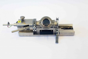
Place the mount plate on a clean workspace. Locate the left alignment mark.
2.
Place the left endcap on the mount plate, aligning the marks on endcap and the mount plate
3.
Place and tighten the left mounting pin.
4.
Place a clamp on the mount plate, with the handle side under the endcap.
5.
Place an O-ring onto the end cap and keep it in place with the reactor housing in your right hand. While holding the reactor housing, close the clamp with your left hand.
6.
Place an O-ring onto the left endcap, and slide the right endcap into place.
7.
Test the assembly by slightly tightening the right mounting pin. The right endcap base should be flush with the mount tool. If the right endcap base is not flush with the mount plate, open the right clamp, tighten the right mounting pin, and close the clamp again.
Use the mounting pins to secure the reactor to the base unit.
9
Switch on the system with the mains switch. The display prompts for confirmation to start the alignment procedure. If the display shows "INTERLOCK ERROR 9", the reactor is incorrectly mounted. Check the reactor, and reassemble if required.
Select "Shut down" from the menu and shut down the system with the mains switch..
Unscrew the mounting pins.
Lift the reactor and transfer it mount plate. Secure the reactor to the mount plate with the mounting pins.
Disassembling and cleaning the reactor
Move mounting plate with the reactor to an environment where risk of particle exposure is limited, such as a fume hood or glove box.
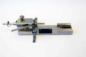
Open and remove the right clamp. Remove the right end-cap and O-right by sliding them to the right. image
Gently wipe the surfaces of the right endcap and the O-ring with a cleaning cloth/wipe, moistened with ethanol, water, or IPA. Use a moistened cotton tip to clean inside tubing. image: gloved hands cleaning with a wipe
Open and remove the left clamp. Remove the reactor housing and O-ring by sliding them to the right.
Gently wipe the surfaces of the reactor housing, left endcap and the O-ring with a cleaning cloth/wipe, moistened with ethanol, water, or IPA. Use a moistened cotton tip to clean inside tubing. For cleaning the viewport, see Cleaning the viewport.
Dry the endcaps, reactor housing and O-rings using filtered pressurized air or a dry cloth. No visible trace of solvent should remain.
It is necessary to periodically clean the left insulator, which is normally left in the fully retracted position when removing the endcap for any reason already described in this manual. If there is too much particle build-up in the reactor there is a risk of electrical damage to the VSP-G1 unit. To clean the hidden insulator surface, the electrode position can be adjusted by turning the gear on the underside of the endcap. image Ensure that all surfaces are dry before reassembly.
To clean the base unit, use a cloth moistened with water, ethanol or isopropyl alcohol.
Warning: Do not spill liquids on the VSP-G1.
Cleaning the viewport:
Warning: The inner side of the viewport is coated with a delicate coating that scratches easily. Wear lint-free or surgical rubber gloves when handling. Do not touch the inner surface.
Notification: The provided viewport clamp reduces operator exposure risk by preventing unauthorized opening of the viewport. Do not use the quick-release clamps for the viewport.
Unmount the reactor, and place the mount tool with reactor on a working surface.
Remove the viewport cover with a gentle twisting motion.
Use a 8 mm wrench to open the viewport clamp.
Carefully remove the viewport.
Clean the inner surface of the viewport window:
Remove large particles with filtered pressurized air.
Remove light smudges by wiping very gently with a lint free optical wipe moistened with IPA
If the window shows serious marks and/or contamination, contact VSParticle
Place the O-ring and viewport cover on the reactor housing, and place the viewport clamp. Tighten with a torque wrench. Do not overtighten.
Filter replacement
Notification: The VSP-G1 does not contain any user serviceable filters. This section covers filters used in the overall system, as described in the Process connections section.
This procedure is entirely dependent on your particular setup and deposition system, but we recommend the use of a HEPA filter or one of higher quality/filtration efficiency. Particle filters are characterized by a drop in filtration efficiency for particles between approximately 100 and 300 nm. For particles smaller than 20nm as generated by the spark generator, filter efficiency is typically >99.99%. In heavy use situations, a high capacity (HEPA) pre-filter can be used to protect a more expensive end filter.
Dispose used filters according to your local disposal guidelines and any particular requirements outlined by the filtration system you choose for your setup. At a minimum, the filters should sealed and labelled in a sturdy plastic bag.
Fuse replacement
Shut down the system, turn off the mains switch, and unplug the cable from the base unit. The fuseholder is located on the back of the base unit between the mains switch and the mains supply plug, accepts 5x20mm T2.5A/250V fuses.


