Occasionally the spark voltage drops suddenly, and a weak arc may be seen between the two electrodes. This is caused by a too high charging current. If this occurs directly after changing the spark voltage or spark current set point, the control system in the VSP-G1 will likely correct the situation. If not, the chosen set point cannot be maintained in spark mode. Increase the spark voltage or decrease the operating current to correct the situation.
==== Interlock errors ====
==== Interlock errors ====
Revision as of 13:50, 22 March 2017
This is the comprehensive User Manual for the VSParticle Generator One Spark Generator (VSP-G1). The Quick Start Guide is available as a quick reference for standard operation and maintenance of the VSP-G1 unit. REVISIT THIS LAST SENTENCE when the manual and QSG are finished. After completing the User Manual, cross-check the residual risks requirements...if any changes are made to information in the residual risks table (8.5), make sure the corresponding changes are made in the design document.
VSParticle Generator One
VSParticle Molengraafssingel, 10 2629JD Delft The Netherlands support@vsparticle.com www.vsparticle.com
top EDIT for content when the manual is finished. Advanced editing: Refer to company website for consistency in language and terminology.
The User Manual provides instructions for the set-up, installation, operation and maintenance of a VSParticle Generator 1 ("VSP-G1") unit.
Warning: Before operating the VSP-G1 unit, please read—and understand—this manual.
Wherever a caution symbol is affixed to the machinery, there are explanatory texts located within the manual (see section 3.2 for a list of all labels on the machinery and the location of relevant information within this manual). Other important safety information located within the manual are also labelled with the caution symbol.
(Short index of manual and a 1 sentence summary of each chapter/section)
1. Introduction
1 sentence summary
2. System and operator safety
1 sentence summary
3. System description
1 sentence summary
4. Setting up
1 sentence summary
5. Operating the system
1 sentence summary
6. System care
1 sentence summary
7. Accessories and replacement parts
1 sentence summary
8. Appendices
1 sentence summary
You will also find conformity and warranty information at the very end of this user manual.
A Quick Start Guide is also included for faster set-up as part of the standard operating procedure. For more information regarding safety, more complex operations and troubleshooting and maintenance, refer to this manual first!
If you have any questions or concerns regarding the VSP-G1 unit you have purchased or any information within the provided user documentation, please contact us:
Address:
Molengraafssingel, 10
2629JD Delft, The Netherlands
Email:
support@vsparticle.com
Website:
www.vsparticle.com
VSParticle Generator One
The VSP-G1 is designed for use by researchers who want to produce inorganic nanoparticles from conductive materials for applications in fields ranging from cluster research to materials science. The VSP-G1 is a desktop spark generator that uses spark ablation technology to produce aerosol nanoparticles after a high voltage spark evaporates part of two metallic electrodes. Its design is aimed at making the production of nanoparticles as simple as possible, while giving you the flexibility to customise the system by having control over:
particle size (1 atom to 20 nm)
ablation rate (~0.01-100mg/h)
carrier gas
electrode material
gas flow rate (1-30L/min)
It is also possible to customise the reactor by changing configurations from through flow (the standard configuration offered with the basic VSP-G1 unit) to cross flow, co-flow and combined configurations. The portability of the system also allows it to be integrated into a larger system for more complex operating procedures.
The VSP-G1 is designed as a continuous source of aerosolized nanoparticles for use in a controlled process system. This controlled process system typically comprises a gas source, a gas-tight system of unit operations, valves and tubing, and a gas exhaust fitted with one or more particle filters. Typical conditions in the process system are room temperature and ambient pressure. The system can be run at slight over- or under-pressure.
The closed system provides a safer production of nanoparticles and can easily be dismantled for safe transport of produced nanoparticles and for system cleaning and maintenance, which can be performed following a simple and fast protocol. The closed system design also allows you to produce high purity nanoparticles without any polluting by-products. The spark ablation process eliminates the use of any chemicals, surfactants, precursors or polymers. Without the need to rely on external materials to stabilise the produced particles, you have more flexibility to choose a suitable deposition system for the aerosol nanoparticles. The three physical principles to inmobilize the nanoparticles on a support are diffusion, impaction and electrostatic precipitation. If you have any questions or need help with the selection and/or development of a system that best fits your needs, please contact us.
The risks associated with a spark generator can be divided into two categories: those associated with the machine itself, and those associated with nanoparticles. Machine-related risks are more widely regulated by international norms, such as the European conformity system required for marking certain products with the CE symbol. However, synthesized nanomaterials are relatively new and their quantum effects are still being studied, thus there are less standardized measures in place. Until more is known about nanoparticles, we apply the Precautionary Principle, treating them as potential highly toxic materials. The safety measures we employ for working with, storing and transporting nanoparticles have been drawn primarily from those designed for fine particles.
Safety of machinery
The VSP-G1 spark generator comprises general electronics (<50 V), gas connections and high voltage (6 kV), as well as moving parts. Several safety mechanisms mitigate the risk for damages and incidents related to potential equipment failure, but primary responsibility for correct and safe operation lies with you as the operator of the system. The VSP-G1 is intended for use by qualified personnel only.
the pressure in the system is limited to ±0.2 bar (see Process connections);
all, if any, external safety systems are functional (where applicable); and
personal protective equipment are being used correctly (gloves, glasses, and FFP3/P3 certified filter mask).
Existing protective features
Warning: Intentional misuse of the VSP-G1 in a manner not specified by VSParticle may impair the existing protective features.
The VSP-G1 is equiped with an interlock system. When a failure is detected, the interlock system cuts power to the high voltage supply and the motor, shutting down particle production. There are three types of interlock.
Warning: Gas connections and other user-provided functions are not controlled by the interlock. An optional external interlock is available for the VSP-G1.
Internal Interlock.
During start-up and while running, the VSP-G1 the control system checks if internal systems are working properly. If any check fails an internal interlock is triggered. When the interlock cuts power, you must first fix the conditions that caused the interlock to activate before clearing the interlock state. Press and depress both dials simultaneously to clear the interlock.
Reactor interlock.
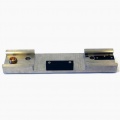
The mounting pin is used both to secure the reactor assembly, and to close the interlock protection.
The VSP-G1 detects whether the reactor endcaps are properly mounted, using two mounting pins (see image). You must ensure that the reactor itself is correctly assembled. In short, this means that the reactor is leak tight (see Leak tightness protocol) and that the gas inlet valve and electrode tips are free to move with a minimum clearance of 10 mm from any foreign objects (see Flow configurations).
External interlock. (option)
An external interlock switch can be provided for incorporation in an external safety system. To allow operation, two pins of the interlock connector must be connected (shorted). Breaking the connection switches the system into interlock mode.
Other residual risks
Pressure. Pressure within the closed system poses a serious risk when improperly handled. Increased pressure can be caused by unintentional release of gas at high pressure, the closing of output valve while the input valve is open, clogged filters, spark obstruction, or a full deposition system. Exceeding the maximum pressure can lead to failure of the gaskets and seals, and the viewport could explode.
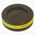
Non-ionizing radiation. The spark plasma emits a bright light in the visible and UV range. A viewport with a removable optical filter is included to allow visual inspection of the electrodes. Additionally, electromagnetic radiation (radio frequency) may be emitted.
Notification: See Residual risks for a comprehensive list of residual risks and how they are mitigated through design features and/or documentation.
Safety of nanoparticles
Because our spark generators can in principle be used to produce nanoparticles from any metal, we start from the assumption that these nanoparticles pose potential risks to the health of operators, consumers and to the environment. This manual addresses operator exposure. Consumer exposure is determined by the application in which the nanomaterials are to be used and should be evaluated on a case-by-case basis by the user. Environmental considerations should also be addressed by the operators with a life cycle analysis.
The main channels of operator exposure to nanoparticles are through (skin) absorption, ingestion and inhalation. The aerosol nature of the produced nanoparticles by the VSP-G1 system means exposure through inhalation is the main risk. The respiratory system of the human body has natural defenses in place for airborne particles such as dust, viruses and bacteria. However, nanoparticles are able to bypass most of these defenses due to their small size. For this reason, nanoparticles are treated in the same way as fine particles. More information on health and safety of nanoparticles can be found through the links at the end of this section.
Operator exposure
While the VSP-G1 unit is designed to be a closed system to maximize safety when working with nanoparticles, there will be situations in which it will be necessary to open the system, including routine maintenance activities, replacement of electrodes and filters, and sample extraction. The list below also includes some possible situations in which the operator may be inadvertently exposed to nanoparticles and a brief summary of the necessary precautions to prevent, wherever possible, such situations.
Exposure risk situation
Operator precautions
Gas phase exposure
An aerosol system must be leak tight from source to deposition (see Leak tightness protocol).
Filtration
The gas exhaust should be treated with a suitable HEPA or ULPA filter. VSParticle recommends using a large capacity HEPA pre-filter, followed by an ULPA end filter.
Dealing with pyrophoric materials
Metal nanoparticles can be extremely reactive, and can be pyrophoric (spontaneous ignition upon exposure to air).Controlled air-exposure, however, is needed before opening the system in order to passivate any reactive materials (see Controlled-air exposure protocol).
Product handling
When the system must be opened to insert or remove a substrate, methods as described in Maintenance must be used to reduce the risk of nanoparticle exposure.
Maintenance
Nanoparticles will collect on the surfaces inside the reactor and downstream piping. Cleaning of these surfaces presents the largest exposure risk to operators, unless they can be performed in a safe environment (e.g. a glovebox) (see System care for the relevant maintenance protocols).
There is also a separate protocol for dismantling and sealing used filters for disposal/recycling, which is largely dependent on your particular filtration system (see Filter replacement).
Life cycle analysis
The waste of the spark generator consists of the carrier gas plus any nanoparticles not deposited on the substrate but picked up when cleaning the reactor surfaces and the pre- and end-filters. These materials should be pooled, preferably separated by the elements in the waste, in order to recycle the metals. The carrier gases are typically inert Ar and N2, which can be vented (e.g. through a fumehood). If other carrier gases are used (toxic, greenhouse, etc), capture or post-treatment should be used to conform to general industry or laboratory standards on gas use.
Life cycle analysis for the end product should be evaluated by the operators on a case-by-case basis.
Links to more information on nanoparticles and health
Nanosafety Guidelines, a set of safety recommendations for working with ‘free nanostructured matter’ in research activities conducted within Dutch Universities
Nanosafety Quick Check, a checklist developed based on a summary of the Nanosafety guidelines listed above is there a link to this, or can we provide this as a downloadable file? permissions?
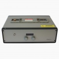
In the box [image of the open box] you will find the following:
The VSP-G1 base unit,
a reactor mounted on the base unit,
a black viewport cover (possibly mounted on the reactor),
a reactor mount plate,
and a power supply cable
You will also find a Quick Start Guide for daily operation and a reference card for working with nanoparticles in the lab. If there's anything missing or looks damaged, contact us immediately! A damaged power supply cable may temporarily be replaced by a similar cable, but ensure it has a functional protective earthing terminal.
Detailed system description
A visual reference and detailed description of the components that are part of the VSP-G1 system is provided on the Detailed System Description page.
Guide to symbols found on the VSP-G1 unit
Below is a full list of the labels affixed to the VSP-G1 unit with a short description and links to relevant locations within this manual for more detailed information.
make some images smaller while keeping the captions in place.
Label
Description
Information location
Location: lower right hand corner of the top of the base unit.
All purpose warning label for the operator to read and fully understand the User Manual (and all warnings) before use.
Refers to the entire User Manual. Information about leak tightness can be found in the Miscellaneous operating protocols section.
Location: on the mount plate underneath the reactor housing.
Do not remove reactor housing when running the spark generator.
See System description: Reactor assembly.
Location: on the inside of the power switch.
High voltage warning.
Warning: DO NOT OPEN THE BASE UNIT.
For service personnel only.
Location (x2): on the screws of the topcaps.
Warranty void if seal is broken to access the power supply in the topcaps.
See System description: Reactor assembly.
Location: on the viewport clamp.
Use this viewport clamp only for attaching the viewport to the reactor assembly.
See System description: Reactor assembly.
Location: on the outer rim of the viewport filter.
UV radiation is harmful to the eyes, do not remove the viewport filter when the spark generator is in use.
See System description: Reactor assembly.
Location: on the outer rim of the viewport.
UV radiation is harmful to the eyes, put the viewport filter on the viewport before running the spark generator.
See System description: Reactor assembly.
Location: on the viewport filter.
Gas inlet connection only.
See System description: Reactor assembly.
Location: on the back of the base unit.
Important technical specification information relevant to running the VSP-G1 unit, contact information, and warning against opening the system (no user replaceable parts).
For information about electrical supply, see Setting up: Electronics; for information about pressure safety, see Basic operating procedure.
Location: on back of the base unit, above the functional earth terminal.
Functional earth terminal for extra grounding protection.
See Setting up: Electronics.
Location: on back of the base unit, above the RS-232 communication port.
Warning: When conducting activities requiring an open reactor, ensure that:
The power is off and the power supply has been disconnected;
There is no gas flowing through the system;
You are wearing safety equipment, including gloves;
The reactor assembly has been moved to a safe environment before it is opened (unless handling for the first time); and that
The internal pressure has been equalised (unless handling for the first time).
Warning: Do not open the base unit. There are no user serviceable parts inside.
Front view of the VSP-G1 base unit
Place the base unit on a flat surface, ensuring sufficient space around the sides and back of the unit for gas, power and communication connections.
Do not connect the system to a power supply until everything has been properly assembled.
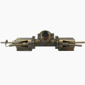
Mounting the reactor assembly
Warning: Under no circumstances mount the endcaps onto the base unit without a sealed reactor.
When shipped, the reactor assembly is attached to the transport plate in the packaging. The electrodes have already been installed. In the case you want to replace the electrodes, please see the electrode replacement protocol (in the System Care section of this manual).
Step
Description
1.
Unscrew and remove the alignment pins holding the reactor assembly to the transport plate.
2.
Holding the endcaps in both hands, carefully transfer the reactor assembly to the mount plate located at the top of the base unit, aligning the markings on the bottom of the reactor assembly's endcaps and the mount plate.
3.
Lower the reactor assembly gently and allow it to slide into position.
4.
Use gentle pressure to ensure the reactor assembly is fully pressed down.
5.
Insert the alignment pins and tighten.
To confirm that the reactor assembly is correctly assembled, use a digital multimeter (DMM) to measure the resistance between the reactor chamber and the ground point on the back of the system. Image needed. The resistance should be <0.1 Ohm.
Process connections
Warning: Important notes about carrier gases:
Do not use reactive gases, in particular gases containing more than a few percent oxygen, such as air.
Do not use heated gases.
Here, we'll discuss a simple set-up using one inlet and outlet using Swagelok connectors. On this page you'll find much more information on the available configurations and connections.
Flow configurations
content needed
Warning: Do not use a rigid gas connection on the gas inlet valve. You can damage the reactor if the valve is not free to move during the homing sequence.
Final set up checklist
Content needed (including ensuring that the system is grounded)
Electronics
Grounding the system
The spark generator uses the ground from the mains plug for safety. Use only certified cables and properly wired wall outlets. The separate functional earth terminal on the back of the base unit (#21 in the base unit back diagram above) is internally connected to the mains connector ground, and should be independently connected to the protective ground in the case a recommended mains power supply plug is unavailable.
Warning: Failure to sufficiently ground the VSP-G1 unit can result in exposure to lethal voltages.
Power supply connections
After assembling the base unit and reactor, plug in the power supply and the communication cable.
Manual controls
content needed
identification and description of operating controls and their use in all operating modes
Warning: Do not open the system while it is being operated remotely.
Your customised setup
Your particular deposition requirements and research needs will result in a system setup that is different from others. In all cases, however, the following requirements help ensure that the system works efficiently and safely:
Working system that allows compartmentalisation of the reactor and the deposition system;
Gas pressure monitoring tool;
Deposition system; and
Safe exhaust (fume hood with HEPA+ filters, for example) for the outflowing gas.
A guide to a reference setup is available to help designing basic setup that fulfills these requirements on the VSP-G1 Reference setup page.
Warning: Please read the entire Basic operating procedure before operating the VSP-G1!
Warning: Do not handle or open the system while particles are being generated and while gas is flowing.
Basic operating procedures
An abridged form of this section is also available as a Quick Start Guide.
Building a simple setup
The following basic operating procedure is for a simple setup pictured below, which comprises several operating units: a gas source and flow system, a particle source (the VSP-G1 unit), a pressure gauge, a deposition system and exhaust filters. To complete the setup, the units are connected with tubes, piping, fittings, valves and so on. The ball valves () in this setup help compartmentalize the overall system for leak testing and for safe disconnection. Each setup will be different, depending on your individual needs, but the concepts described here should generally be valid.
A simple setup connecting the input gas source and flow system to the particle source, deposition system, filtration system and the ventilation system.
Modify image: Pressure sensor should go upstream, add feedback to flow system
To reduce particle losses, please take the following guidelines into account:
Keep the tubing length between particle source and deposition system as short as possible to reduce diffusive losses.
Use conductive tubing (metal or conductive polymer) in particle carrying lines to reduce electrostatic losses.
Do not use flow controllers (e.g. needle valves, mass flow controller) in particle lines, as particles will clog up the controller.
Usually the controller can be placed in another (particle free) line, or downstream of the deposition system, behind a filter.
If flow control is absolutely needed in a particle line, use an orifice.
Avoid constrictions that can function as a particle trap. I particular:
Use ball valves with a wide bore.
Avoid fibers and meshes.
[TC: IS THERE A CODE FOR AUTOMATICALLY RESIZING THE IMAGE BASED ON BROWSER SIZE? USEFUL FOR OPERATORS ACCESSING MANUAL USING TABLETS IN THE LAB]
Building a setup takes three steps:
Design/draw/sketch your flow diagram, including sensors, valves and filters.
Assemble the rest of the setup according to your flow diagram.
Check the system for leak tightness and make adjustments if necessary. (See Checking for leaks.)
Compartmentalisation
For safety reasons, we recommend compartmentalisation of every unit within the setup that regularly opens up to the atmosphere to allow for easy dismantling in a safe manner. In the setup described here, we use two valves on both sides of the deposition chamber which allows us to easily seal off both the reactor and the rest of the setup. When the deposition chamber is removed, it can be safely transported to a safe working location, such as a fumehood or glovebox, in order to take out the sample. Meanwhile, the rest of the setup, which often contains a significant amount of nanomaterial, remains safely sealed.
Pressure safety
Warning: Do not exceed +1.2 bar absolute. Do not turn on the spark below 0.8 bar.
The internal pressure should not exceed +1.2 bar or there is an increased risk of failure of the gaskets and/or seals in the reactor, causing leaks and risk of nanoparticle exposure. A build-up of pressure within the system might be an indicator of obstruction, either within the reactor, the deposition system or in the filtration system. Ideally, a pressure sensor at the reactor inlet is used to automatically switch off the gas supply. Stop spark production and gas flow immediately when pressure reaches +1.2 bar to determine the source of obstruction and resolve the issue. See System care for cleaning procedures.
Checking for leaks
Warning: The leak tightness protocol is an essential part of the operating procedure before initiating particle production. Failure to test for leak tightness, improper installation/removal of blindcaps or lack of external monitoring tools could mean the total output of the system—that is, up to 100mg/h of nanoparticles—is released continuously to the operator.
Start nanoparticle production
Ensure that the system is leak tight.
Power up all systems.
Ensure that the path to the exhaust is clear.
Start gas flow.
Set target voltage and current using the dials on the front of the VSP-G1 base unit.
Press the start button to begin production.
To stop production, press the start button again.
==== Stabilising the system ==== We recommend leaving the system to equilibrate/stabilise for 15-30 minutes, depending on your specific needs. This time allows the system to warm up, and the surface of the electrode tips to be refreshed and removing, if any, surface oxides.
Remove your sample
All four valves on both sides of the deposition system have been closed (highlighted in red) to contain it for removal from the setup.
When the deposition system is full or when you’ve produced the desired amount of nanoparticles,
Take out your sample following the procedure for your deposition system, taking the necessary precautions to prevent/reduce exposure to nanoparticles.
To remove our sample in the setup above, we stopped particle production, flushed the system (9 x τ), closed off the four valves surrounding the deposition system (see image to the right... or link to view image on another page) and disconnected the deposition system from the setup. We then took the deposition system, still closed, to the fume hood where we could proceed to remove our sample safely.
find an appropriate location for this section. It was an information box and I removed all information boxes by incorporating all of the text within the overall document. This is the only one I couldn't find a way to make FIT.
Ways of making the system safe before opening:
Flush the system.
Depressurise the system.
Stop gas flow.
Miscellaneous operating protocols
Leak tightness protocol
Testing for leak tightness is an essential part of preparing the system for particle production to optimise safety and minimise unnecessary exposure to nanoparticles.
After checking the flow connections, ensure that the pressure gauge is turned on (and functioning), close the system (see diagram of a sample setup below), slowly turn on the gas flow until the system is full (before it reaches +0.4 bar), and turn it off. The internal pressure should remain the same if the system is leak tight and you can proceed to "Start nanoparticle production".
Step 1: Closing the system before starting the leak tightness protocol.
If the pressure decreases, there is a leak within the system. Release the pressure within the system before isolating the leak to resolve it.
Start with the first enclosed system after the input gas flow. In the next diagram based on our basic setup, the first system we check is the VSP-G1 unit (our particle source). Compartmentalise this section from the rest of the setup by closing the valve following the particle source. (In our case, we turned off the valve immediately after the pressure gauge so that we wouldn’t need to disconnect anything.) Check the pressure by turning on the gas flow slowly and turning it off. If pressure remains constant after the gas flow has been stopped, this section is leak tight and you can move on to step 5.
Step 3: Partial compartmentalisation of the particle source to check for leak tightness.
If pressure decreases, however, check that all connections are sufficiently tightened (if you open any connections, make sure that you’ve turned off gas flow and/or lowered pressure to a safe level). Tighten the connections and/or replace the tubing wherever necessary. Repeat the procedure until the pressure remains constant after the gas flow is turned off.
Repeat these steps for every enclosed section (see diagram below) of the setup until the system is leak tight.
Step 5: Compartmentalisation of the particle source and deposition systems to check for leak tightness.
After completing the leak tightness protocol and resolving any leaks, test the leak tightness of the whole system by opening all valves and then closing the last valve (using the same set up as shown in Step 1).
Once the entire system is leak tight, it is ready for nanoparticle production.
If leaks persist:
Check the proper installation of the blind caps and the pressure gauge connections;
Try using soap solution: carefully apply a soapy solution to the external surface of every possible joint (especially the valve connectors). Where there’s a leak, bubbles should form. If this does not reveal the leak, do the same test on the external surfaces of the tubing for possible leaks; and/or
Check your filtration system: the procedure for checking leak tightness of the filtration system varies depending on how it is set up.
Controlled-air protocol
Warning: Small metal nanoparticles can be extremely reactive. Spark-generated particles made in clean gases can be pyrophoric, presenting a risk of fire when suddenly exposed to air.
content neededgradually introduces small amounts of air to stabilize the system before opening
Flushing the system
Warning: Flushing the system greatly reduces the risk of nanoparticle exposure when opening the unit for any reason.
To reduce risk of operator exposure, the system should be flushed before opening. The easiest way to flush is by flowing gas with the spark switched off. The time required to flush the system depends on residence time (τ),
the volume V of the system (operating volume of the VSP-G1 is approximetly 0.3 L, and the flow rate Qv. As a general guideline, one should flush the system for at least 9 times the residence time. With a flow rate of 1 L/min, this takes about 3 minutes.
Warning: Important points to remember when conducting maintenance activities involving disassembly and reassembly:
Turn off the spark generator and disconnect it from the power supply;
Transport the reactor assembly with the transport plate and open it in a safe environment;
Do not apply pressure when wiping the surface;
The coating on the viewport filter screens electromagnetic radiation. Do not scratch the coating, nor replace it with a different type;
Dry all surfaces before reassembly;
Retract the electrodes sufficiently to avoid collision with each other; and
Screw down both alignment pins.
When to clean the reactor and replace the filter(s)
Clean the reactor whenever you replace the electrodes, the reactor is dirty, or after 100-1000 hours of operation (which in turn depends on your operating conditions: if making more particles, clean more often). If higher settings are needed to maintain a spark flow, it is possible that the reactor needs to be cleaned to prevent spark obstruction which can possibly lead to spark misfiring within the reactor system. If the pressure within the system increases even with the valves open, it is possible that the filter is full and needs to be replaced.
Maintenance protocols
TVP and Vincent: consider adding how-to videos
General
The windows of the viewport and viewport cover and the electrical contacts in the reactor ends and the base unit are fragile. Regular use maintenance includes the removal of generated particles left in the reactor and the replacement of electrodes.
Cleaning the viewport
The inner side of the viewport is coated with a delicate coating that scratches easily. Wear lint-free or surgical rubber gloves when handling. Do not touch the inner surface. To clean the inner surface of the viewport window:
Remove large particles with filtered pressurized air.
Remove light smudges by wiping very gently with a lint free optical wipe moistened with IPA
If the window shows serious marks and/or contamination, contact VSParticle
There are several possible issues that may arise during normal operation of the VSP-G1. A more thorough description of all error codes and ways to resolve these are listed in the Troubleshooting guide.
Glow mode
Occasionally the spark voltage drops suddenly, and a weak arc may be seen between the two electrodes. This is caused by a too high charging current. If this occurs directly after changing the spark voltage or spark current set point, the control system in the VSP-G1 will likely correct the situation. If not, the chosen set point cannot be maintained in spark mode. Increase the spark voltage or decrease the operating current to correct the situation.
Interlock errors
Message on display
Cause
Resolution
Interlock err. 7
Motor controller failure
The motor controller reports a failure. This can be due to:
A blocked motor. Follow the instructions described on the Maintenance protocols page to dismount and disassemble the reactor. Then, verify that the electrode is free to move by manually rotating the gear located at the underside of the left end cap. Assemble and remount the reactor ensuring some space exists between both electrodes and power on the VSP-G1 to try again.
Motor controller communication interference or failure. Press both dials to clear the error and try again. Optionally, switch the machine off and on again. If the error persists, contact VSParticle.
Motor controller failure. Press both dials to clear the error and/or switch the device off and on again. If the error persists, contact VSParticle.
Interlock Error 8
Broken interlock switch
One of the interlock switches is broken or has a broken connection. Verify both reactor mounting pins are properly secured and that the reactor is properly mounted on the base unit. Press both dials to clear the error and try again. If the error persists, contact VSParticle.
Interlock Error 9
Open interlock switch
One or more interlock switches are in the open state. Verify both reactor mounting pins are properly secured and that the reactor is properly mounted on the base unit. Press both dials to clear the error and try again.
Electrode alignment
When the VSP-G1 starts aligning electrodes during start-up, several sounds may be heard:
Quick hammering. This occurs occasionally when the electrode is in an unusual position (e.g. after maintenance/cleaning of the reactor has been performed) and cannot move in the expected direction. This is normal. The sounds should not last more than a second and the system corrects itself and completes the alignment procedure. If the sounds persist for more than a few seconds, switch off the VSP-G1 using the main power switch at the back. Follow the instructions for a blocked motor found under the Interlock err. 7 entry of the interlock errors section above.
Clicks. These occur at the boundaries of the adjustment range and are no cause for concern.
Vibrations or rattling. This can occur when there is tension on the gas inlet of the left end cap, restricting free movement or due to wear of the transmission. Check that the gas inlet is free to move. If these sounds occur regularly, contact VSParticle.
When the electrode alignment sequence fails, this is displayed as Interlock err. 7. Refer to the interlock error section above for possible resolutions.
Use only VSParticle approved parts. All parts related to the reactor assembly must be examined and/or supplied by VSParticle. Contact us for more information.
Specifications of replaceable parts that can be obtained by other suppliers: Fuses - The fuse holder accepts 5x20mm T2.5A/250V fuses. Power cable - IEC-content needed. RS-232 cable - any standard RS-232 cable is suitable.
Additional information about the VSP-G1 operating window, electrical specifications and output can be found on the Technical Specifications page.
Environmental Conditions
The VSP-G1 is designed to be safe under the following normal environmental conditions:
Indoor use;
Altitude up to 2,000 m;
Temperature 5 °C to 40 °C;
Maximum relative humidity 80 % for temperatures up to 31 °C decreasing linearly to 50 % relative humidity at 40 °C;
Mains supply voltage fluctuations up to ±10 % of the nominal voltage;
Transient overvoltages up to the levels of overvoltage category II;
Temporary overvoltages occurring on the mains supply; and
Pollution degree 2.
Detailed communication set up
Configurations Command syntax Command list
Protocol index
set this up as a table with the relevant location within the user manual (in case people decide to print out the manual... the location should be hyperlinked)
edit content
Protocol
Purpose
Location
Assembly
cell 2
4. Setting up
Grounding the system
cell 2>
4. Setting up
Inserting or removing substrate
cell 2
5. Operating the system
Operating procedure
cell 2
5. Operating the system
Leak tightness
cell 2
5. Operating the system
Controlled air exposure
cell 2
cell 3
Flushing the system
cell 2
5. Operating the system
Shut down
cell 2
cell 3
Fuse replacement
cell 2
6. System care
Electrode replacement
cell 2
6. System care
Filter replacement and disposal
cell 2
6. System care
Cleaning the reactor
cell 2
6. System care
Disassembly
cell 2
6. System care
General disposal guidelines
cell 2
6. System care
Incorporation of VSP-G1 into a flow system
cell 2
5. Operating the system
Residual risks
Situation
Risk Category
Possible Hazard
Mitigation of Hazard
Setup
Nanoparticle exposure
Blind caps are not delivered already installed. If they are installed improperly, they might result in nanoparticle exposure.
User action: installing blind caps to the appropriate places. User manual: warning about improper installation of blind caps (5.1); leaktightness protocol (5.2).
Setup
High voltage exposure
Failure to explicitly ground the unit through the protective earth terminal can result in exposure to lethal voltages if the main connection provides no or bad grounding protection.
User action: grounding the unit through the protective earth terminal. User manual: information about grounding the unit (4.4); warning about not grounding the unit (4.4).
Setup
Nanoparticle exposure
Not carrying out the leaktightness protocol can lead to possible nanoparticle exposure if there is a leak.
User action: leaktightness protocol. User manual: leaktightness protocol (5.2); warning about nanoparticle exposure (5.1).
Setup; Operation
Nanoparticle exposure, explosion risk
Overpressurization during leaktightness protocol can lead to explosion of the viewport and compromising the gaskets, leading to possible nanoparticle exposure.
User action: ensuring that there is a pressure sensor connected to the setup and it is functioning. User manual: warning against overpressure (5.1). Marking: pressure limit information label on base unit.
Operation
Reactor damage
Using the wrong gas settings or reverse flow of gas can reduce the lifetime of the reactor.
User action: ensuring that correct gas settings are used and prevention of reverse gas flow. User manual: warning against use of wrong settings or reverse flow (WHERE?). [content needed]
Operation
Reactor damage
There is a risk of damage to the setup if a rigid gas connection is used on the inlet only valve, due to the movement of the valve during the homing sequence.
Design feature: Display asks for confirmation before initiating the homing sequence. User manual: warning against the use of a rigid gas connection on the inlet only valve (4.3).
Operation
Fire risk
There is a fire risk when working with very pure carrier gas (oxygen free) and metal nanoparticles.
User action: ensure (introduction of) small amount of oxygen in the system before opening. User manual: warning of fire risk without flushing the system; list of ways to safely open the system (5.1).
Operation
Nanoparticle exposure, gas exposure
Opening the viewport or blind caps during operation can expose the user to nanoparticles and carrier gas.
Design feature: an additional screw on the viewport clamp makes it more difficult for the operator to deliberately remove the viewport. User manual: warning against removal of viewport and blind caps during operation (5.1). Marking: warning label on the viewport.
Operation
High voltage exposure
There is a risk of exposure to lethal voltages if the topcap of both endcaps are opened.
Design feature: special tool is needed to unscrew the top plate of the endcaps. User manual: warning against opening the top of the endcaps (3.1.1). Marking: high voltage warning labels on both topcaps on the reactor endcaps.
Operation
High voltage exposure, gas exposure, nanoparticle exposure
There is a risk of exposure to lethal voltages, carrier gas and nanoparticles if the spark is enabled (remote/local) when the setup is opened without proper shutdown.
Design feature: unit display will indicate that the unit is being operated locally. User can push a button on the unit to cancel remote operation. User manual: warning against working with the unit while it is being operated remotely (4.5).
Operation
Reactor damage
There is a risk of damage and/or injury when using heated carrier gas. (Environmental temperatures are specified, but not gas specs).
User manual: warning against use of heated gas (4.3).
Cleaning and Maintenance; Storage and Transport
Nanoparticle exposure
Risk of nanoparticle exposure when: reactor is opened outside safe environment; the system is not properly vented when the gas is disconnected; reactor is dropped.
Design feature: use of the transport plate provides stability to the reactor and its clamps, helping reduce risk of opening the reactor by accident while transporting it to a safe environment. User manual: proper procedures for shutting down the reactor and preparing it for disassembly and transport to a safe environment (4.5, 5.1, 6.2). Marking: Warning to read and understand the User Manual before use.
Cleaning and Maintenance; Storage and Transport
Reactor damage
Risk of reactor damage if it is accidentally dropped.
Design feature: use of the transport plate helps reduce risk of damage to the reactor in the case that it is dropped because it keeps all the potentially detachable components together. User manual: warning to use the transport plate whenever handling the detached reactor (3.1.2).
Cleaning and Maintenance
Reactor damage
Using the wrong solvent and/or solvent film on the insulator can result in a short circuit and a broken reactor.
User manual: proper procedure for cleaning the reactor, including appropriate cleaning supplies (6.2). Marking: Warning to read and understand the User Manual before use.
Cleaning and Maintenance
High voltage exposure, nanoparticle exposure
Exchanging the easy-open clamp with the viewport clamp (which requires a tool) poses a risk because the viewport can then be opened easily during operating resulting in high voltage and nanoparticle exposure.
User manual: describes the risk of not having a viewport in place (3.1.1); describes the proper clamps to use for the viewport (3.1.1). Marking: warning labels on the viewport warn against removal of the viewport while the spark generator is running; label on clamp labeling it as the viewport clamp.
Storage and Transport
Nanoparticle exposure
There is a risk of nanoparticle exposure when the unit is shipped or stored without cleaning it.
User manual: protocol for preparing the unit for storage and transport (6.3 and 6.4). [content for 6.3 and 6.4 needed]
Theoretical background
Overview of nanoparticle research
Nanoparticles are unique in the way that their size changes their material properties. The properties can change due to quantum effects, or simply because their large surface area increases reactivity. As we continue to understand more about the quantum properties of nanoparticles, we can begin to appreciate the possibly endless applications of nanoparticles. If we look at the scientific literature published in the last five years, there are six major areas of scientific study focusing on the application of nanoparticles (FOOTNOTE: compiled using the Scopus database https://www.scopus.com/): catalysis, sensors, electronics, coatings, energy and health. The highest number of publications are from the fields of catalysis, health and energy, with energy research containing the most subfields. Another area not as widely studied as the six mentioned above, (but has interesting potential), includes the application of nanoparticles in lubricants to improve lubricant performance.
The subfields of nanoparticle application research within the six areas and their possible industrial [commercial?] applications include:
Field
Subfield
Possible applications
Catalysis
New catalysts
Atomic mixing enables the creation of completely new alloys and materials with improved catalytic activity.
Impregnation of supports
Spark discharge can be used to impregnate nanoparticle-sized catalytic support, which greatly improves surface area and has already been applied in catalytic converters in cars.
Sensors
DNA/RNA detection
By attaching small pieces of DNA or RNA to a MNP, the complementary piece of that DNA can be detected, which is useful in medical diagnostics or genetic modification.
Gas sensors
Sensors can be made much more sensitive by using MNP's and can be applied to many gases.
Bio-sensors
MNP's can be used to improve bio-sensors that detect organic compounds.
Electronics
Printed circuits
MNP's can be deposited in a pattern or lines to create electronic circuits.
Flexible electronics
The circuits are thin enough to be flexible and can be deposited on any surface, even fabrics.
Photodetectors
( ) ask Joost to expand on this...?
Coatings
Functional coatings
Surfaces could be modified with MNP's to create a transparent, functional coating, which could produce energy, be self-cleaning or be hydrophobic.
Anti-corrosion coatings
Depositing layers of AlO makes the underlying metal more oxidation resistant.
Energy
Fuel cells
Integrating Platinum or Palladium NP's as catalysts in fuel cells could make them more efficient.
Solar cells
Using quantumdots in solarcells could make efficiencies possible above 40%.
Water splitting
Gold MNP's can improve photochemical water splitting.
Hydrogen storage
Magnesium nanoparticles are a promising candidate for efficient Hydrogen storage.
Lithium-ion batteries
Using NP's in batteries improves charging time and the lifetime of the battery.
Health
Anti-microbial coatings
Incorporating silver MNP's in fabrics makes the fabric anti-bacterial, a procedure that is relatively easy to do with spark discharge.
Cancer treatment
MNP's are being used in research for new cancer drugs and to improve chemotherapy. How? Be a little more specific
In-vivo imaging
NP's can be used for medical imaging, as contrasting agents in MRI or other techniques.
Toxicology
Testing the toxicology of nanoparticles can be made faster and easier using spark discharge.
Nanoparticles come in different forms, from dendrimers and composites to carbon-based and metal-based materials, and can be stored in different media, from films to colloids and aerosols. There are different methods based on the form of nanoparticles desired. Meuller and his colleagues summarized the methods of gas phase production of nanoparticles in their review of spark discharge generators (2012), which included flame spray pyrolysis, spray protolysis, electrospray, evaporation/condensation of material and aerosol generation by spark discharge. All methods except for electrospray produce high purity nanoparticles with narrow size distribution at a high production rate. The well-proven electrospray method, which deposits the colloidal particles in a controlled homogeneous manner that minimizes residues where still present, has been in use for a longer time compared to other methods with readily available materials on the market. Both spray protolysis and spark discharge methods are simple and fast. The evaporation/condensation method offers detailed control over deposition parameters. The spark discharge method can easily be scaled up, using more sparks per time or multiple sparks in parallel. The flame spray pyrolysis, evaporation/condensation of material and spark discharge methods all require higher amounts of energy. In the case of the evaporation/condensation of materials, the time and energy consumption required limit the overall operation time of the generation system. The spray protolysis and electrospray methods require the use of precursors and solutes, potentially contaminating the process. Flame spray pyrolysis requires postprocessing for the production of non-oxide nanoparticles. Depending on the desired end product or process, each method has their own set of advantages and disadvantages.
Production method
Summary
Flame spray pyrolysis
High purity nanoparticles and narrow size distribution at a high production rate. Requires higher amounts of energy and precursors in most cases need to have physical properties that are not too dissimilar. Postprocessing is most often required for the production of non-oxide nanoparticles.
Spray protolysis
A simple and fast process for the production of high purity nanoparticles and narrow size distribution at a high production rate. Precursors and solutes are necessary, which potentially contaminate the process.
Electrospray
Deposition of colloidal particles in a controlled homogeneous manner that minimizes residues where still present. Precursors and solutes are necessary, which potentially contaminate the process.
Evaporation/condensation of material
Good yield and offers detailed control over deposition parameters. Energy consumption and the longer heat up and cool down times of the furnace limit the overall operation time of the generation system.
Aerosol generation by spark discharge
Simple method that provides a reasonable yield of high purity nanoparticles with less contaminants involved in a process that can be easily scaled up. Requires higher amounts of energy.
Table based on Meuller, et al. (2012): 1256-7.
Aerosol generation by spark discharge
From the perspective of researchers interested in studying material properties, the spark discharge method provides nanoparticles in a fast, simple manner that eliminates any other contaminants that prevent the study of the pure quantum properties of the nanoparticles. From an industrial (commercial) perspective, the spark discharge method provides a way of producing and depositing nanoparticles directly onto the final product, avoiding issues of transportation and stabilization of mass-produced nanoparticles.
The spark discharge process(based on Meuller et al., 2012) ASK TOBIAS FOR CLARIFICATION ON THE PROCESS AND CLEAN THIS UP
The spark discharge generator is composed of two primary components - the chamber that houses the electrodes and the electric circuit required to control the spark generation.
As the particles from the evaporated electrode material are carried further away from the plasma channel, they coalesce into larger particles.
need to edit the graphic to include labels for the different sizes of the coalesced particles The electrodes are mounted with a gap in between them. A certain amount of electricity (voltage) is required to create a high electric field that accelerate the electrons and cations (on the surface of one electrode?), causing electrons to be knocked out and creating a chain reaction that results in the formation of a plasma channel that is able to conduct the electricity between the two electrodes. The resulting sparks cross the gap from one electrode to another, evaporating the electrodes into a vapor of gaseous electrode material. As the vapor forms, the resulting material stabilises itself due to adiabatic expansion (Hinds, 1982; Tabrizi et al., 2009), radiation, and thermal conduction below the evaporation temperature (Tabrizi et al., 2009). In the tight space around the plasma channel, the particles coalesce into larger forms. However, as the temperature of the particles cools, their size becomes more stable. This is where the use of the carrier gas becomes important. The role of the carrier gas is not only to cool the particles (and thus controlling their size), the gas also keeps the reactor chamber cool and moves the particles away from the plasma channel. The quantum properties of the new particles can cause them to react with the carrier gas, which means the type of carrier gas used is also relevant. Using an inert gas helps maintain a stable atmosphere for the particles during formation and in "storage".
In research applications in which the material properties of the nanoparticles are of primary interest, the produced nanoparticles are stored in a substrate (such as? paper? etc) designed to the research needs of the scientists. For industrial applications, however, maintaining the material properties of the nanoparticles usually requires their deposition directly where they are needed within the production process. An example of this would be creating a product that is self-powering by creating nanoparticles with photovoltaic properties and spraying them onto the surface of the product as the particles are produced.
Research using spark discharge technology
Applications of spark discharge technology in various fields. Give examples, do not be exhaustive.
History of the spark discharge technology (how does our machine improve on the original design?)
Health Council of the Netherlands. Health significance of nanotechnologies. The Hague: Health Council of the Netherlands, 2006; publication no. 2006/06E. Available online. Set up to open in new window
Hinds, W.C. Aerosol Technology: Properties, Behaviour, and Measurements of Airborne Particles. Wiley & Sons, New York, 1982.
Hoeneveld, D. et al. Nanosafety Guidelines. Delft University of Technology: NanoSafety workgroup of the Faculty of Applied Sciences, 2008. Available as downloaded document. Set up to open in new window
Meuller, B. O. et al. Review of Spark Discharge Generators for Production of Nanoparticle Aerosols. Aerosol Science and Technology, 2012. doi: 10.1080/02786826.2012.705448.
Tabrizi, N.S. et al. Generation of nanoparticles by spark discharge. J. Nanopart. Res., 2009; 11:315-332.
MISC TEXT From research to commercial applicationsThis might not be a good place for this... move this to website
There are few applications imaginable where a single, free nanoparticle would be relevant. The value of nanoparticles lies in the quantum properties that enhance more tangible products, such as improving drug delivery methods at the cellular level or creating more efficient solar cells. However, the same quantum properties that makes these particles interesting present a drawback at the industrial level - not much is known about the quantum properties. Some nanomaterials are perfectly safe, but other nanomaterials might be even more toxic. Currently there is no method of predicting whether or not a specific particle (size, shape, composition) would present a health hazard.
Moreover, handling of nanoparticles is not trivial. It's very difficult, if not impossible, to separate two particles once they touch without the use of surfactants or other chemistry. Most nanomaterials are desired for their purity and particular deposition state, thus it is cost-ineffective and time-consuming to produce nanomaterials, collect them for shipment, separate them, and incorporate them into a product in yet another process, rather than to produce the nanoparticles in-line and deposit them directly where they are needed. The VSP-G2 is being designed for direct integration into the industrial production process. Are there other nanoparticle "generators" that can be directly integrated into the industrial production process?
EC Declaration of Conformity
top version for user documentation does not need to show signature nor serial number
Note: I left all of the warning labels from the original draft of the user manual. Not all have been inserted into the document itself. These can be edited for an "Important Safety Guidelines" document to be shipped with the new VSP-G1 unit. - Kate
Warning: Explosion risk: Do not exceed +0.4 bar. Do not turn on the spark below -0.4 bar.
Warning: Fire risk: The VSP-G1 is not intended for use with reactive gases, in particular gases containing more than a few percent oxygen, such as air.
Warning: Reactor damage risk: Do not use heated gases as carrier gases.
Warning: Intentional misuse of the VSP-G1 in a manner not specified by VSParticle may impair the existing protective features.
Warning: Gas connections and other user-provided functions are not controlled by the interlock.
Warning: Do not use a rigid gas connection on the gas inlet valve. You can damage the reactor if the valve is not free to move during the homing sequence.
Warning: Ensure that your pressure gauge is working properly before operating the system.
Warning: The optical filter on the viewport is designed to protect your eyes against the intense UV light of the spark. Do not remove the filter when running the spark generator.
Warning: Failure to follow protocol or lack of external monitoring tools could mean the total output of the system—that is, up to 100 mg/h of nanoparticles—is released continuously to the operator.
Warning: Do not handle or open the system while particles are being generated and while gas is flowing.
Warning: VSParticle does not recommend the use of air or other oxygen-rich gases for nanoparticle production in the VSP-G1 unit.
Warning: Do not use the power supply in the topcaps as an outlet.
Warning: When conducting activities requiring an open reactor, ensure that the power is off, and that the reactor assembly has been moved to a safe environment before it is opened, to avoid possible nanoparticle contamination. If pressure has not been equalised, there's also a chance of explosion.
Warning: {{{2}}}
Warning: Do not remove the filter on the viewport, which provides eye protection. If the viewport needs to be cleaned, make sure the spark generator is turned off and the reactor has been relocated to a safe environment.
Warning: Improper installation of blind caps on the unused valves can result in possible user exposure to nanoparticles and carrier gas.
Warning: High voltage risk: do not open the base unit. There are no user serviceable parts inside.
Warning: Do not replace the detachable mains supply cords with inadequately rated cords.
Warning: If the power cable provided with the VSP-G1 unit is not functional, please use a power cable with an integrated protective earthing terminal. Otherwise, take measures to ensure that the system is earthed. (See "Grounding the system" below.)
Warning: Foreseeable misuse: xx
Warning: Ensure that all surfaces are dry before beginning assembly of the G1 unit.
Warning: Under no cirumstances mount the endcaps without a sealed reactor, such as the one provided. The reactor should be conductive, preferably metal.
Warning: Always screw down both alignment pins.
Warning: The mains supply has protective earthing, but always ground the system using the external functional earth terminal, which provides additional protection in case the first set of protections fail to work.
Warning: The leak tightness protocol is an essential part of the operating procedure before initiating particle production.
Warning: Please read the entire procedure before using the VSP-G1!
Warning: The spark generator should not be running during this procedure or you risk unnecessary exposure to nanoparticles!
Warning: Ensure that you are wearing safety equipment including gloves when working with an open reactor.
Warning: Do not apply pressure when wiping the surface.
Warning: Ensure that all surfaces are dry before operating the spark generator!
Warning: When reassembling, make sure to retract the electrode sufficiently to avoid collision with the right electrode.