VSP-G1 Detailed System Description: Difference between revisions
T.coppejans (talk | contribs) (Created page with "== Reactor assembly == full|none|The VSP-G1 reactor assembly, external view. {| class="table table-bordered table-striped" |- !...") |
T.coppejans (talk | contribs) m (T.coppejans moved page VSP-G1 System Description to VSP-G1 Detailed System Description without leaving a redirect) |
(No difference)
| |
Revision as of 11:32, 22 March 2017
Reactor assembly

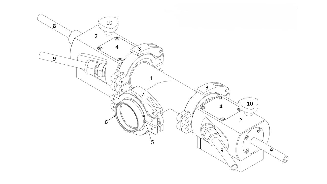
| Part no. in drawing | Description |
|---|---|
| 1 | Reactor housing |
| 2 (x2) | Endcaps |
| 3 (x2) | O-rings and clamps |
| 4 (x2) | Topcaps |
| 5 | Viewport |
| 6 | Viewport filter |
| 7 | O-ring and clamp for the viewport (opened/closed with a tool) |
| 8 | Gas inlet valve |
| 9 (x3) | Gas valves (inlet or outlet) |
| 10 (x2) | Alignment pins |
| Blind caps (4x), not pictured |
The reactor of the VSP-G1 is where all the action happens during spark generation. It is also the area of highest risk to high voltage, nanoparticle and gas exposure, and UV exposure.
Notification: It is very important that all safety guidelines for the reactor are followed carefully.
The reactor assembly is easily removed from the mount plate (#11 in the base unit diagram below) for cleaning and other maintenance activities to be conducted in safe conditions (such as under a fume hood). The removal of the O-rings and clamps (#3) on either side of the central reactor housing (#1) allow access to electrodes for replacement and cleaning.
The endcaps (#2) contain the power supply to the motor powering the reactor. The power supply is accessible by the topcaps (#4), for VSParticle service personnel only.
The viewport (#5) allows you to do a visual check of the electrode tips (Cu electrodes come with the standard VSP-G1 unit, already mounted in the reactor housing) without opening the reactor housing. It will be necessary to remove the viewport for cleaning and maintenance activities, but under normal conditions the viewport must be kept in place to reduce the risk of exposure to high voltage and nanoparticles. For this reason, the viewport is attached to the reactor using an O-ring and clamp (#7), which can only be removed by the use of a tool. The viewport filter (#6) can be removed from the viewport for a better view of the electrodes, but it is necessary to keep the filter in place during operation due to UV radiation given off by the spark.
The unit is packed with four blind caps (not pictured) to be installed on any of the four valves (#8 and #9 in the above diagram) that will not be used in your setup. It is important that the left valve, labeled "INLET ONLY" (#8), is only used for a gas inlet connection. It is also important that the connection is flexible, allowing the valve freedom of lateral movement during the homing sequence.
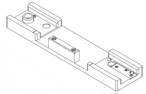
Transport plate
| Warning: Always mount the dismounted reactor assembly to the transport plate to reduce possible damage when handling it for maintenance activities. |

The transport plate is similar to the mount plate that connects the reactor to the base unit, but it contains ledges that help ensure that parts of the reactor are aligned properly when opening/closing the clamps (#3). It provides a stable surface for working with the dismounted reactor and/or transporting it to a safe environment for maintenance activities.
For your safety and to minimize risk of dropping/damaging the reactor, ensure that you always:
- attach the reactor to the transport plate using the alignment pins (#10);
- work with the disconnected reactor in a safe environment, such as under a fume hood; and
- wear gloves to protect the internal surfaces of the reactor housing and to prevent open exposure to nanoparticles.
Base unit
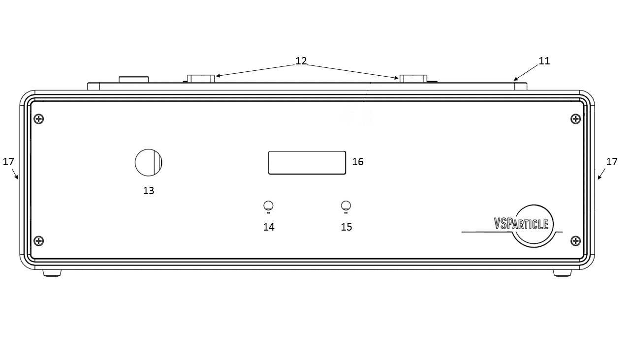
Image of the front view of the base unit was changed on 31 January to show #17 on both sides of the unit (handholds). Make sure that this image is visible on this page.

| Part no. in drawing | Description |
|---|---|
| 11 | Mount plate |
| 12 (x2) | Alignment plates |
| 13 | Start/Emergency stop button |
| 14 | Spark energy adjustment knob |
| 15 | Spark frequency adjustment knob |
| 16 | Display |
| 17 (x2) | Handholds (on each side of the base unit) |

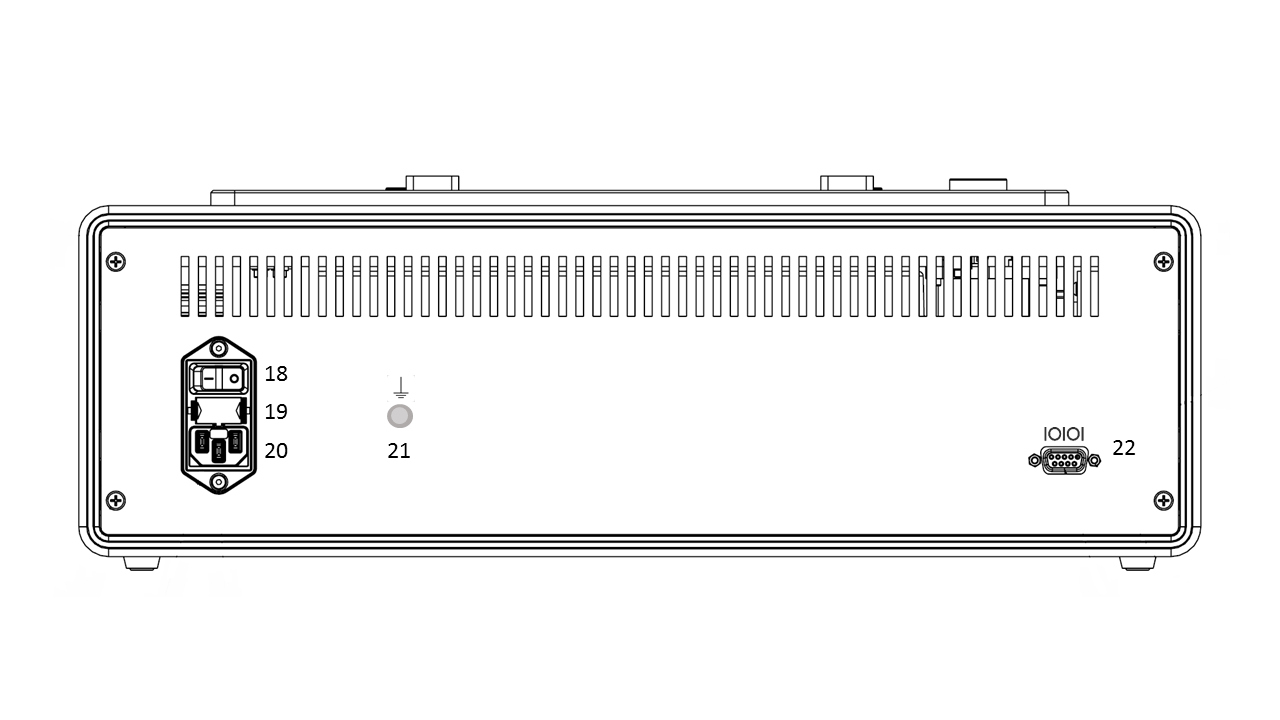
| Part no. in drawing | Description |
|---|---|
| 18 | On/off switch |
| 19 | Fuseholder |
| 20 | Mains supply plug |
| 21 | Functional earth terminal |
| 22 | RS-232 port |
The base unit contains the motor for operating the spark generator. The base unit also contains the manual controls for fine tuning the operation of the spark generator, from spark frequency (#15) to the amount of power to the spark production (#14). On top of the base unit is the mount plate for connecting the reactor housing to the base unit. The alignment plates (#12) help ensure the reactor is aligned properly when mounted. Using the handholds on the sides of the base unit (#17), please place it on a stable flat surface that provides free physical access to the gas input and output valves (#8 and #9), and provides freedom of access to the power controls and plug (#13, #18, and #20).
The on/off power switch (#18) as well as the connection plugs for power (#20), communication (#22) and fuse (#19) are located on the back of the base unit. Also located on the back of the base unit is a functional earth terminal (#21). The fuseholder accepts 5x20mm T2.5A/250V fuses.
Other
image(s)
Power Cable with ground - this cable provides the power supply to the system while grounding the system against electrical surges that might cause electrical shock. If the power cable provided with the VSP-G1 unit is not functional, please use a power cable with an integrated protective earthing terminal. Otherwise, take measures to ensure that the system is earthed (such as using the functional earth terminal, #21). (See also Grounding the system.)
